|
|
Gunsumer Reports TM Providing Detailed Objective Reviews for Firearms and Firearm Accessories |
Akdal MKA 1919 Shotgun Review
Part 5 - Internal Features
April 9, 2012
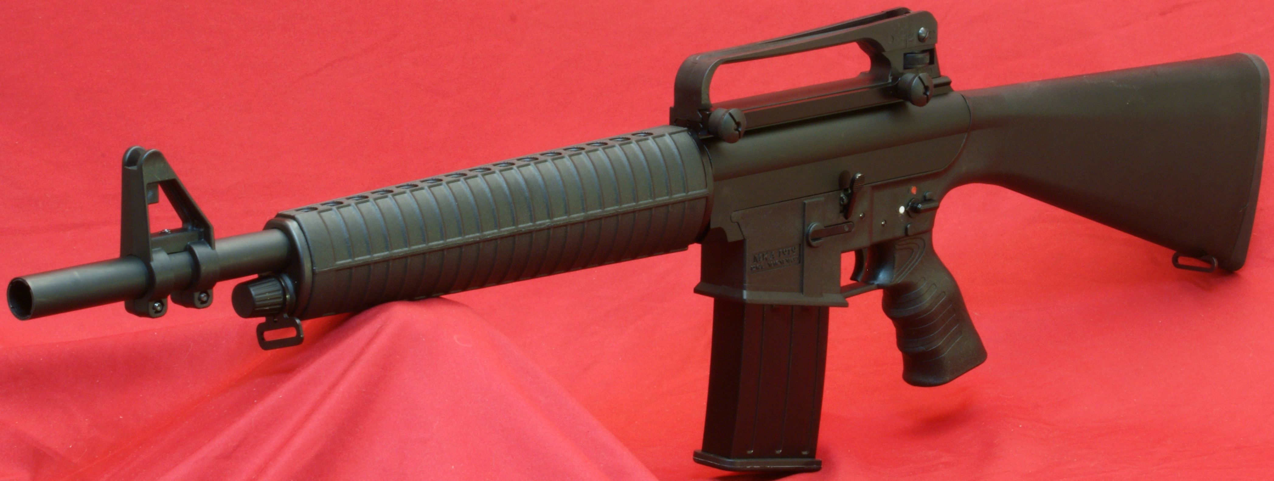
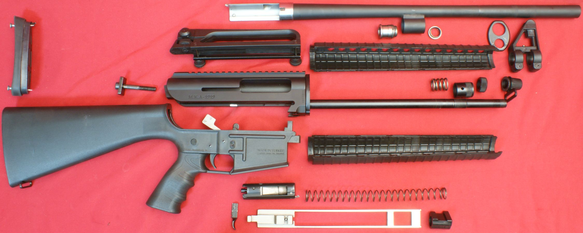
In Part 4 of my Akdal MKA 1919 Shotgun Review I disassembled the shotgun to the level you see below. In this part of the review I'm going to show each of these components/assemblies and comment on the significant internal features. I may not comment on every photo, but I have included them for your own study. Remember that you can click on any photo to bring up a higher resolution photo showing the details in greater clarity.
Figure 1
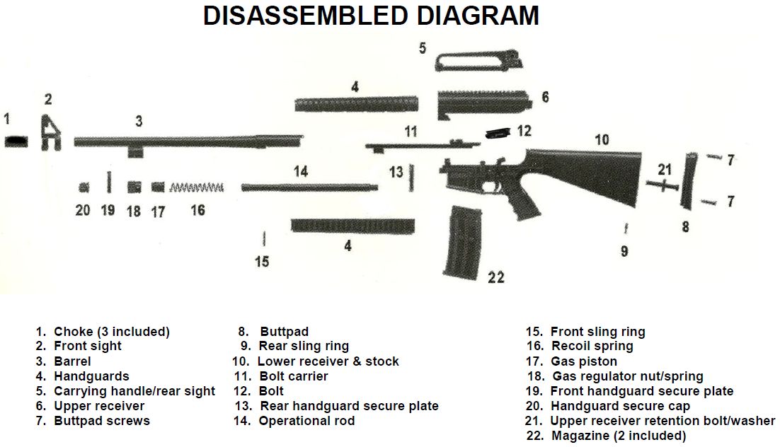
The figure below comes directly from the Owner's Manual for the MKA 1919 Shotgun and the numbered items in the figure are listed below. I have tried to cover each of these parts in the order listed on this parts list.
Figure 2
|
|
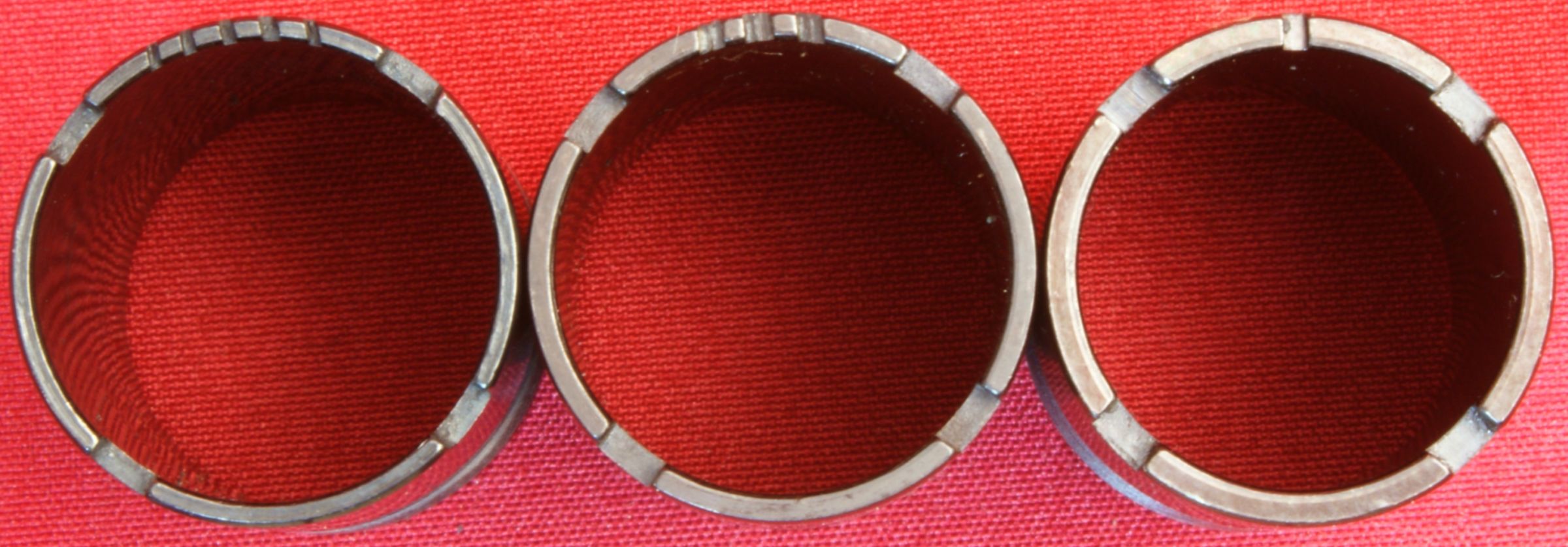
1- Chokes
I already covered this in Part 3 but have included it here also for completeness. The MKA 1919 Shotgun has an internal choke system and comes with three chokes, choke wrench and case. The chokes are marked with notches on the end. A 12 gauge shotgun has an un-constricted bore of 0.729" in diameter. The values below compare the ideal internal choke diameters against the measured diameters for the chokes that came with this shotgun. In all cases, the measured diameter was within 0.003" of the ideal diameter which in my mind says the chokes are properly marked and the constrictions match what you would expect for each choke.
- 1 Notch - Full - Ideal 0.694", Measured 0.691"
- 3 Notches - Modified - Ideal 0.709", Measured 0.712"
- 5 Notches - Cylinder Bore - Ideal 0.729", Measured 0.726"
Figure 3
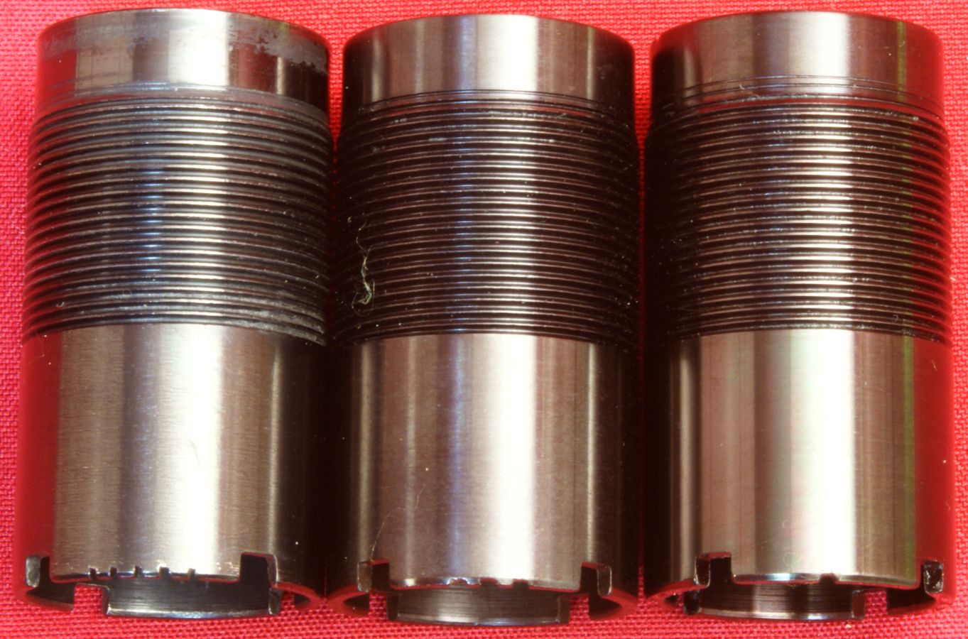
Figure 4
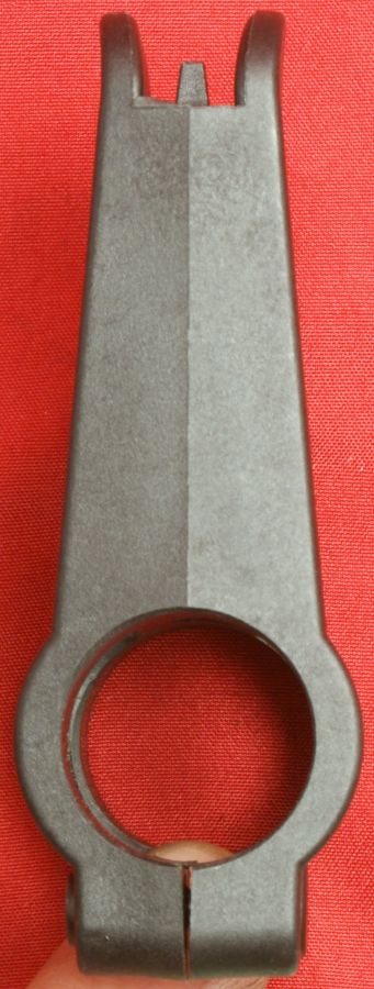
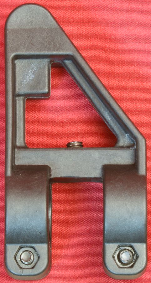
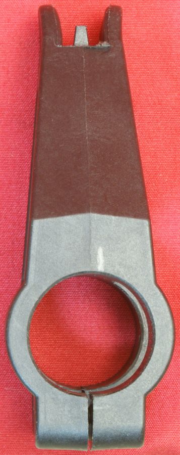
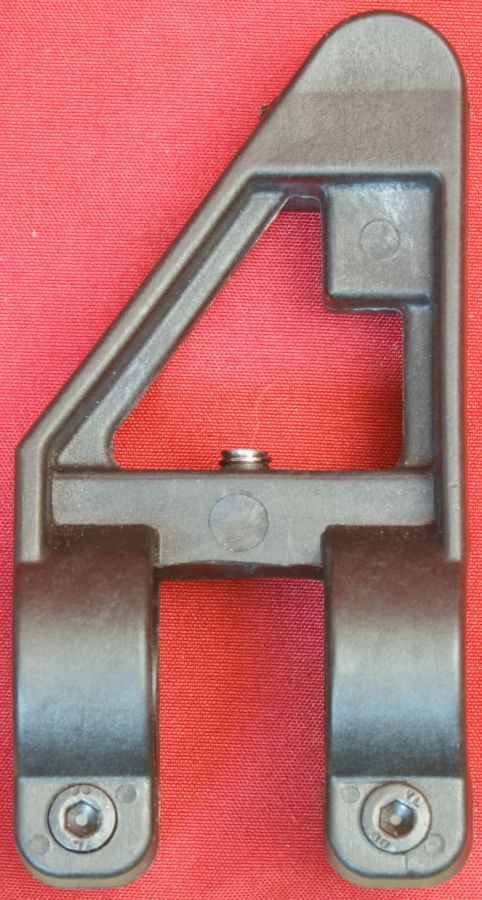
2 - Front Sight
The front sight is an all polymer sight that clamps around the barrel and has a set screw to assist in preventing rotation of the sight.
Figure 5
Figure 6
Figure 7
Figure 8
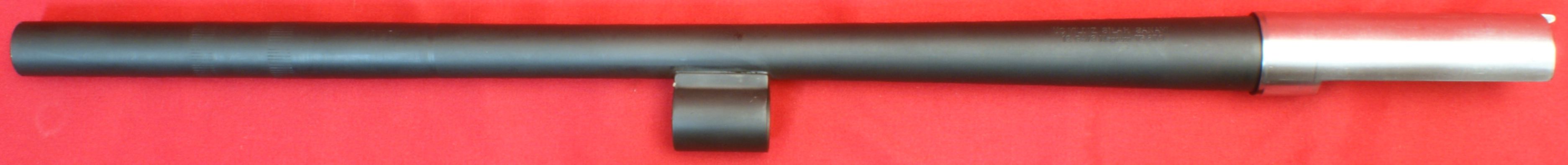
3 - Barrel
The MKA 1919 Shotgun comes with a steel 18.5" barrel with a matte blued finish. The barrel has a lower lug brazed (welded) to that barrel which is used to attach the barrel to the operating rod and provides a porting path and a chamber for the gas pistol.
Figure 9
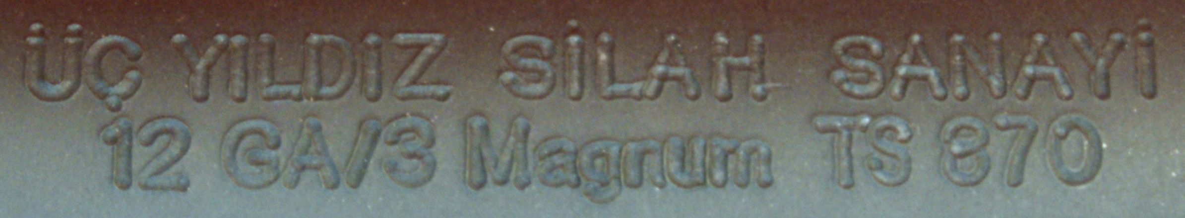
The left side of the barrel near stamped "ÜÇ YILDIZ SILAH SANAY" on the top line and "12 GA/3 Magnum TS 870" on the bottom line as shown below. The top line identifies the manufacturer and the bottom line identifies the gauge, shell type and the TS 870 indicates that the barrel has been proof tested to 1200 kg/cm2 which is 17068 psi.
Figure 9a
From the rear of the lug, you can see the two gas ports. On the front of the lug is the spring loaded ball which is used to help prevent rotation of the gas regulator nut.
Figure 10
Figure 11
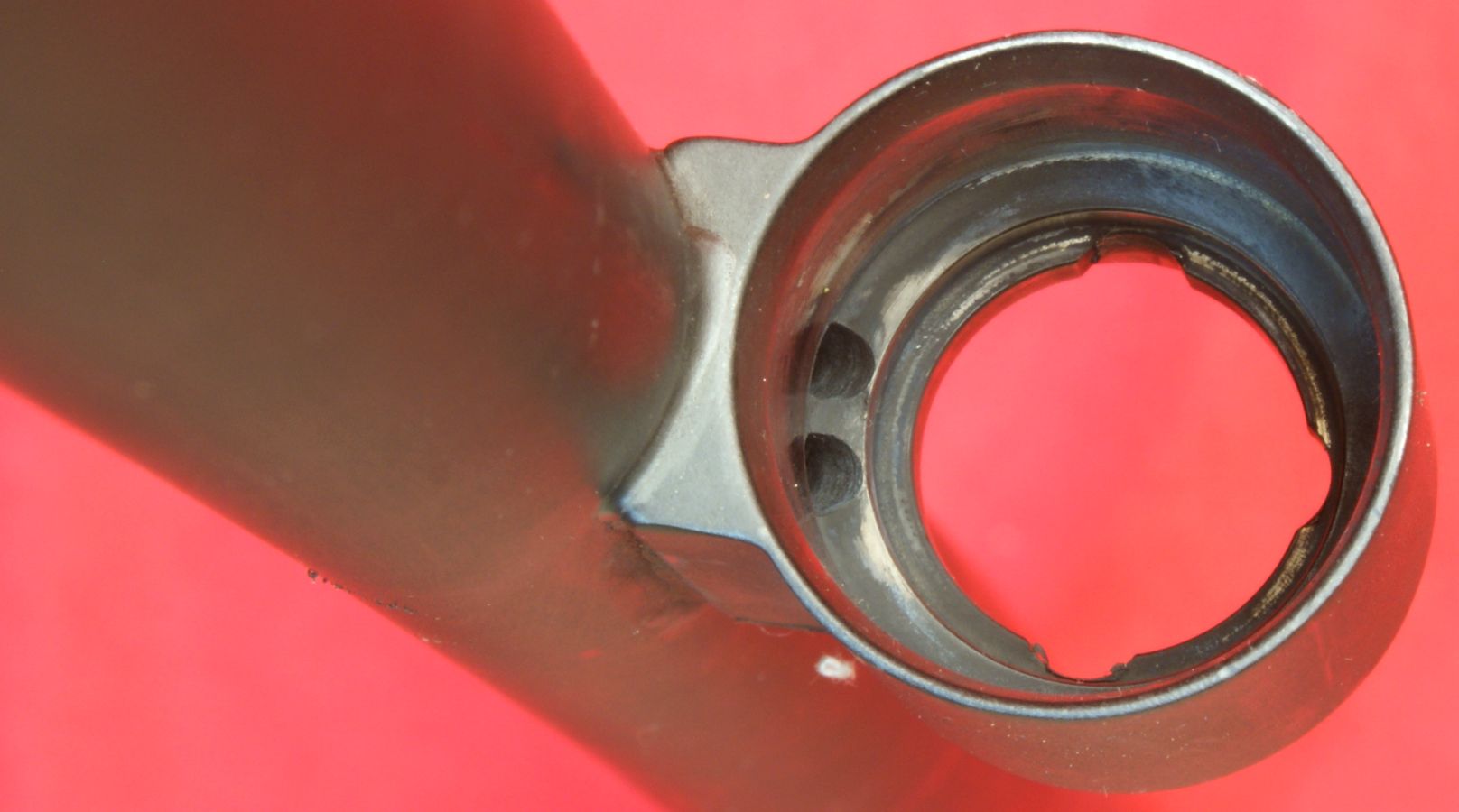
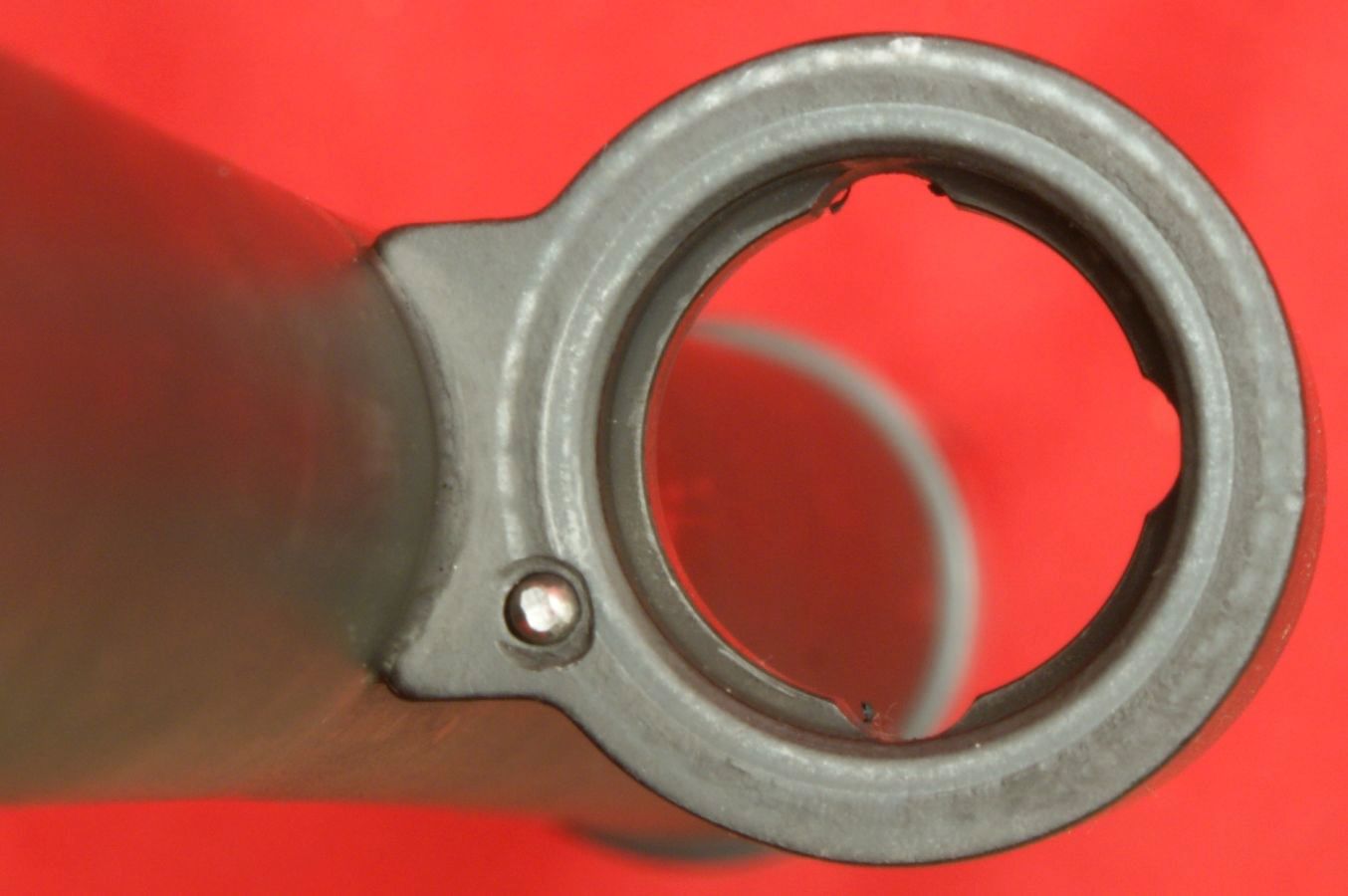
Figure 12
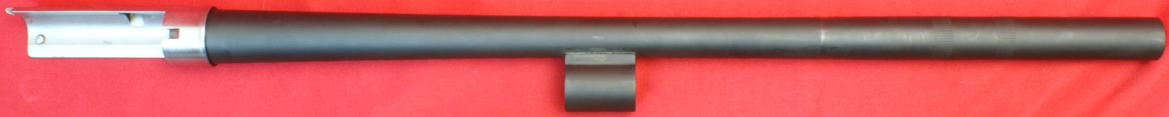
The barrel has a rear stainless steel barrel extension that mates inside the upper receiver when the barrel is installed on the shotgun.
Figure 13
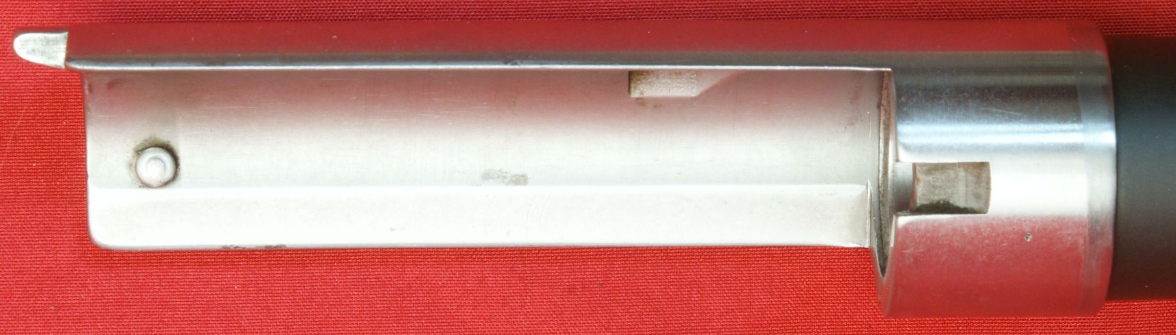
On the inside of the barrel extension you see a pin used to guide the bolt, the recess for the locking block, and the notch for the extractor.
Figure 14
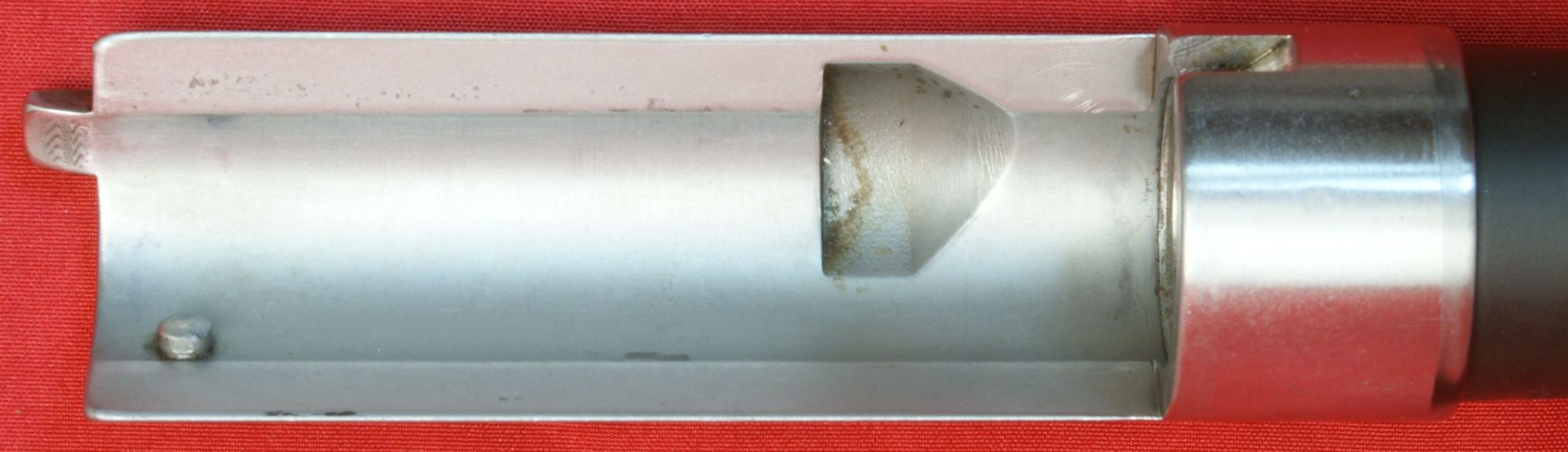
Figure 15

Looking into the barrel chamber you see that the chamber appears to have a rough surface, but actually this surface was very smooth to the touch.
Figure 16
The front of the barrel is internally threaded to accept internal chokes.
Figure 17
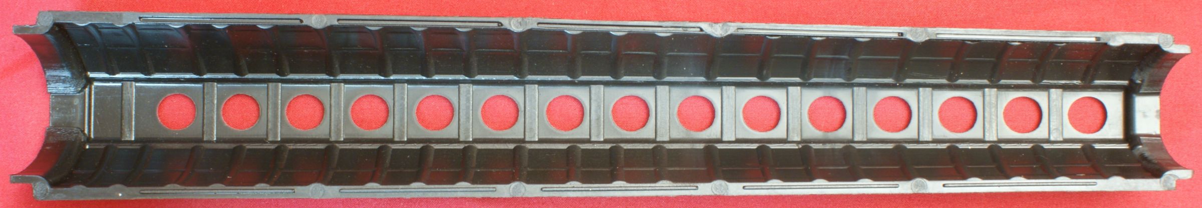
4 - Handguards
The handguard is actually a two piece polymer handguard where both pieces are identical. The handguard has an oval shape with the barrel taking up the space in the top of the handguard and the operating rod, barrel lug and gas piston taking the space in the lower portion.
Figure 19
Figure 20
Figure 21
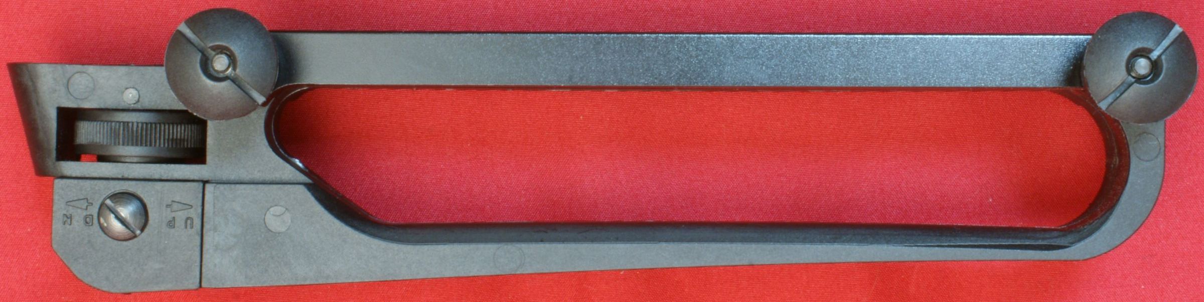
5 - Carry Handle/Rear Sight
These next several photos show the different sides of the carry handle rear sight. It is a polymer part with an aluminum clamp plate. The rear sight is adjustable in both windage and elevation.
Figure 22
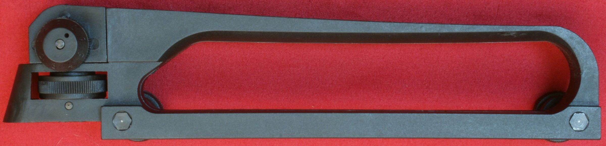
Figure 23
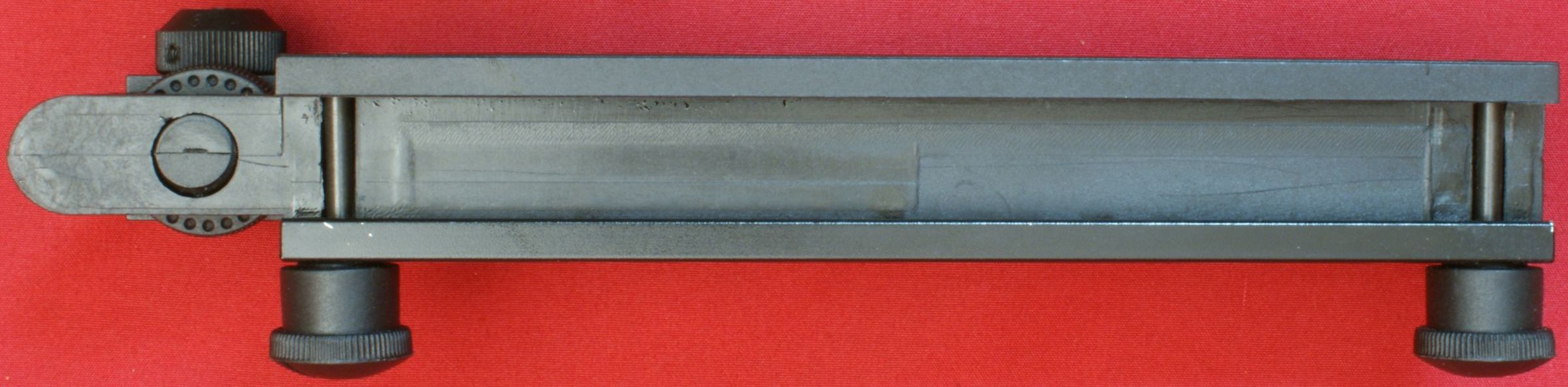
Figure 24
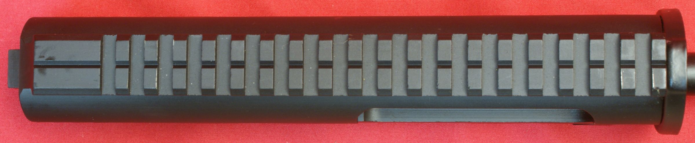
6 - Upper Receiver
The upper receiver is machined from an aluminum alloy. The top has a 19 slot integral Picatinny rail that measures about 8.5" in length including the rear area without slots.
Figure 25
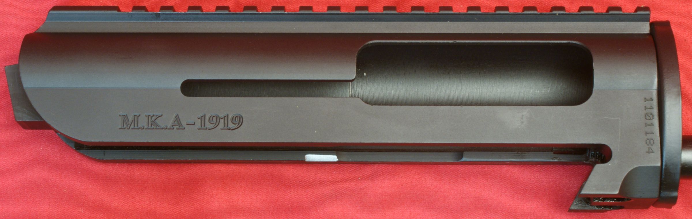
In the photo below, you can see that the bottom inside of the receiver on the left side has had a portion filed off (shiny looking area) after the anodizing was applied. Most likely this was some type of post production modification. I believe this modification has something to do with the bolt catch lever being able to rotate fully up. The bolt catch lever did work perfectly on this shotgun.
Figure 26
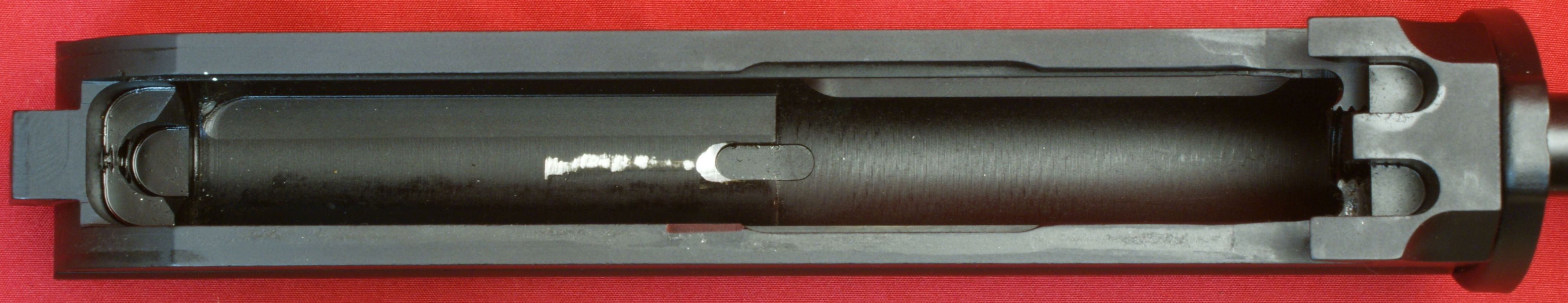
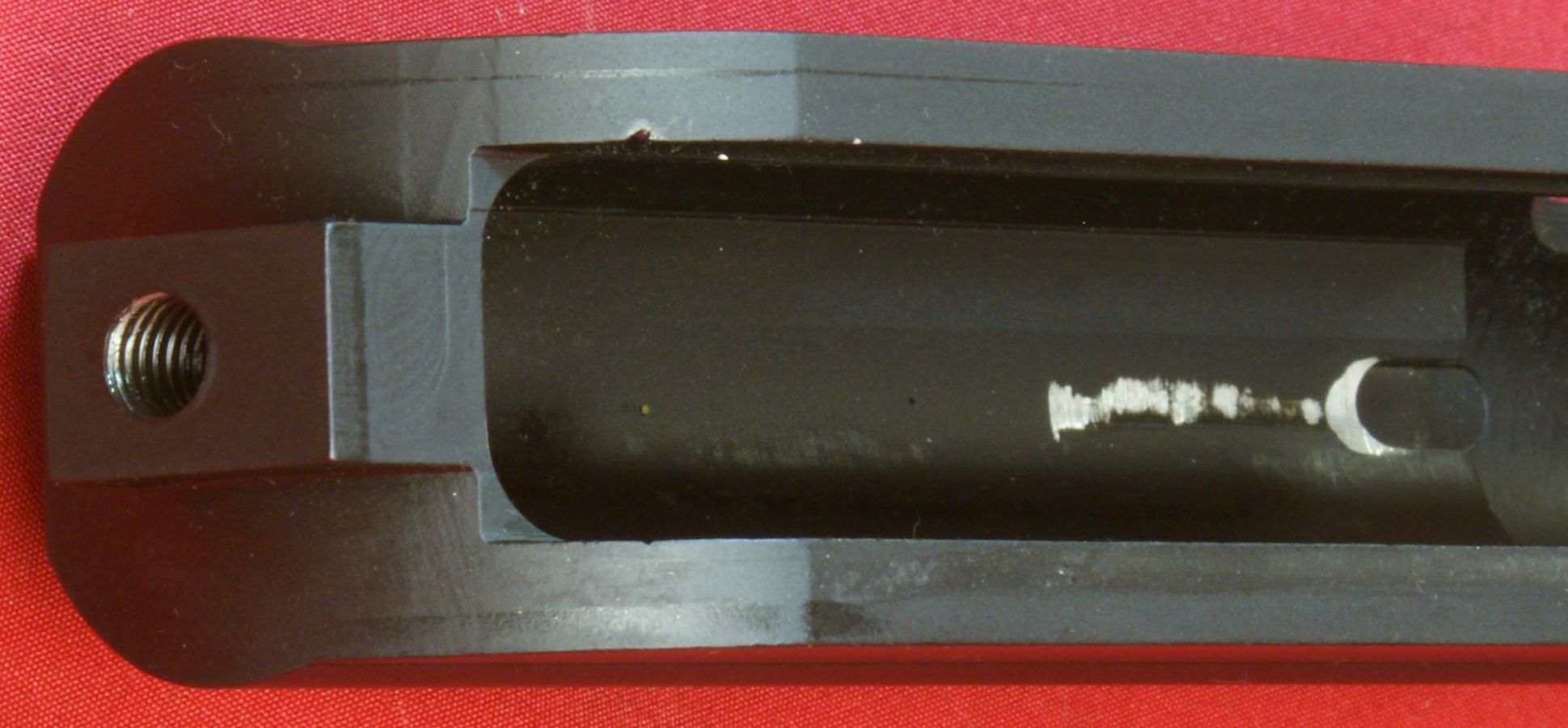
Since this shotgun was a review firearm provided by RAAC, there was no requirement to send a completely new shotgun and I'm positive it has already seen several more rounds than just a couple proof rounds. The first indication was when I disassembled the shotgun for Part 4 of the review. I always do this prior to shooting any ammunition to show the "as received" condition of a firearm and also to get a good set of photos prior to dirtying things up. Although the shotgun had been cleaned (somewhat) prior to sending it to me, you could tell it had seen several rounds. The second indication was the wear marks on the inside upper surface of the upper receiver shown below. I will discuss this more in Part 6 of the review when I show the range test results, but until then, this photo below shows the initial wear condition of this shotgun prior to me shooting any shells.
A positive feature to point out in the photo below is the beefiness of the aluminum upper receiver. I like the fact that it has thick sides and top walls. The top wall in the area of the wear is extremely thick and this wear should have no impact on the strength of the receiver.
Figure 27
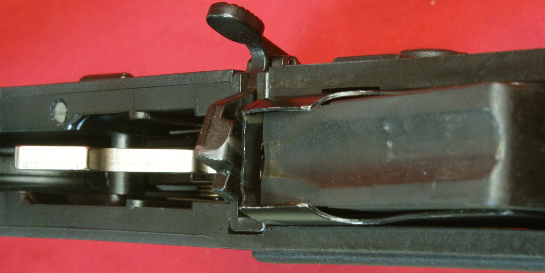
These next couple of photos give you a good look at the lug on the foreword end of the upper receiver which mates with the lower receiver. You can see how the lower receiver tucks under the lug to hold them together.
Figure 28
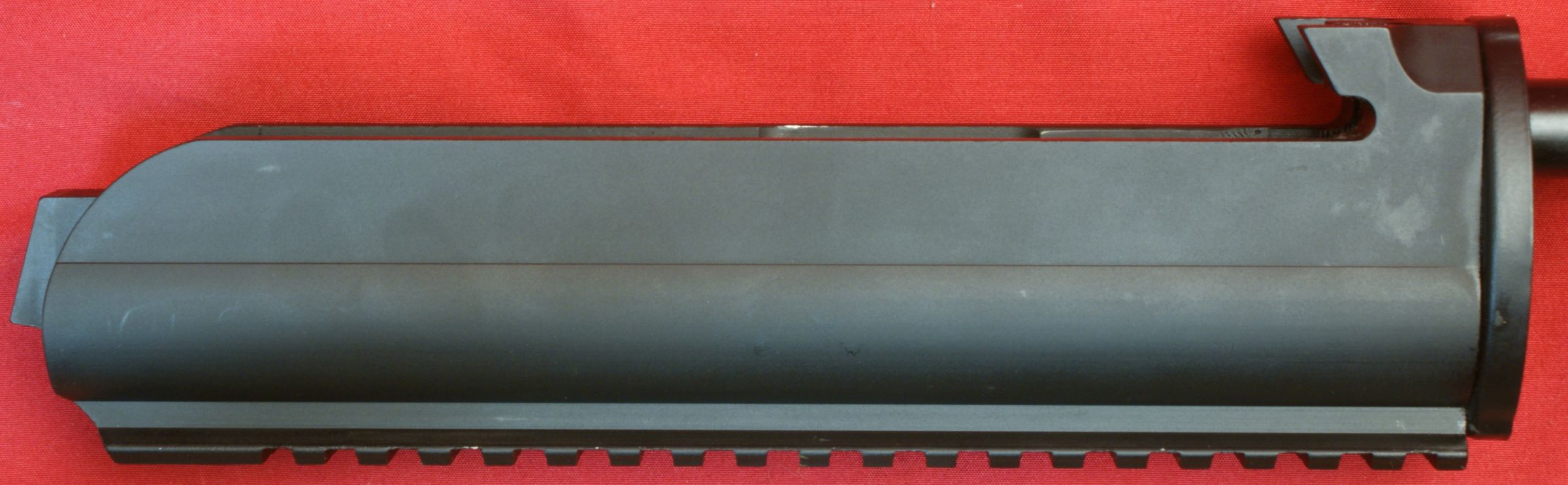
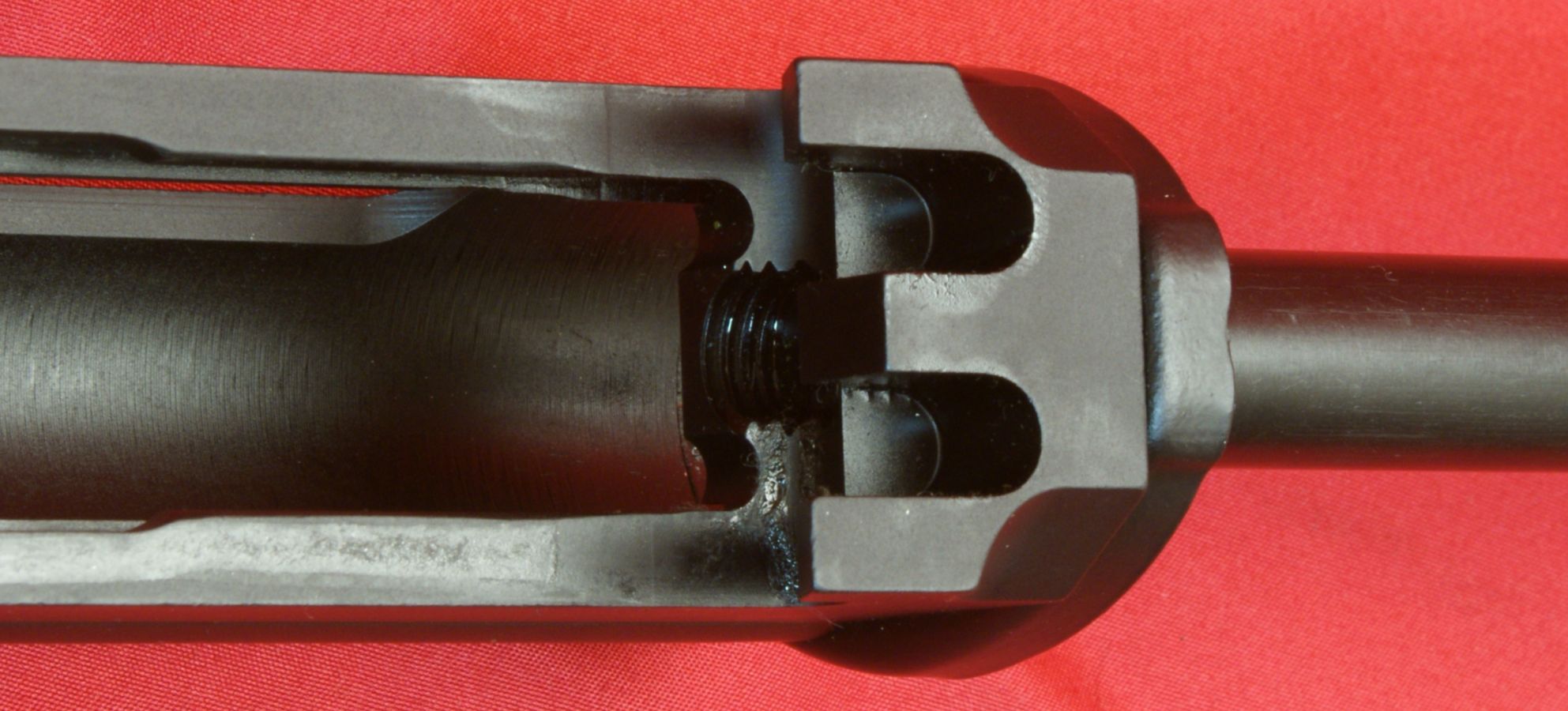
In this photo below, the two "U" shaped slots provide the side-to-side indexing of the two receivers and hold them securely in that position. You can also see the internal thread for the operating rod. I tried to unscrew the operating rod by hand, but was unable to do so (a good thing).
Figure 29
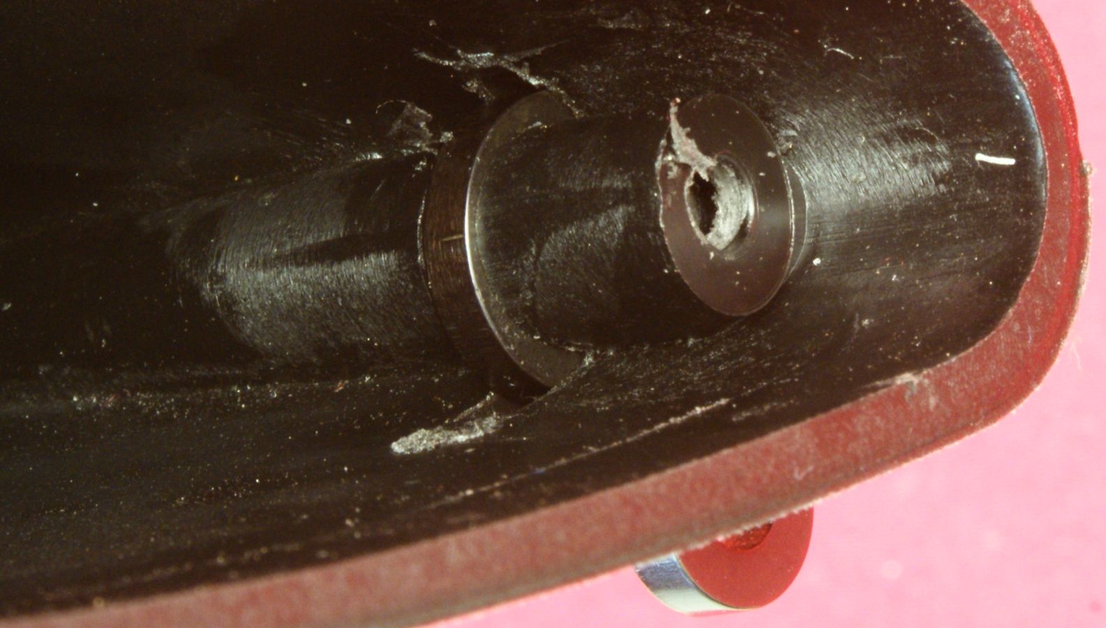
The rear of the upper receiver has a lug/pad to allow for longer thread engagement on the upper receiver retention bolt. Considering you must remove the retention bolt to remove the bolt and carrier from the shotgun, I wish they would have installed a steel thread insert at this location in the receiver to prevent wear and reduce the potential for damage of the threads.
Figure 30
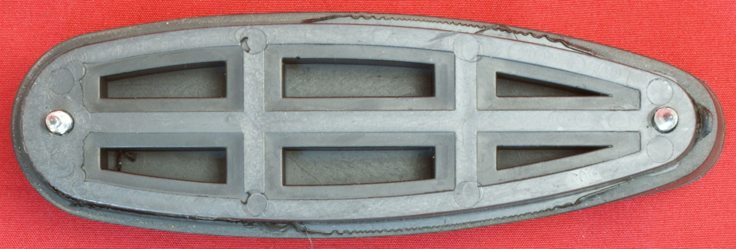
7 - Buttpad Screws & 8 - Buttpad
Like most shotgun buttpads, the buttpad on the MKA 1919 has a molded polymer frame with rubber molded on top. The rubber is of a good hardness/softness for a recoil pad, but I feel a little more thickness would be appreciated by most. The two screws appear to be made from stainless steel.
Figure 31
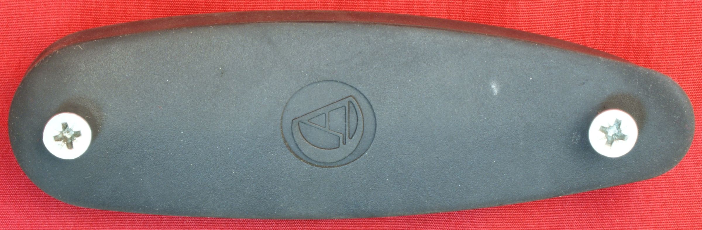
Figure 32
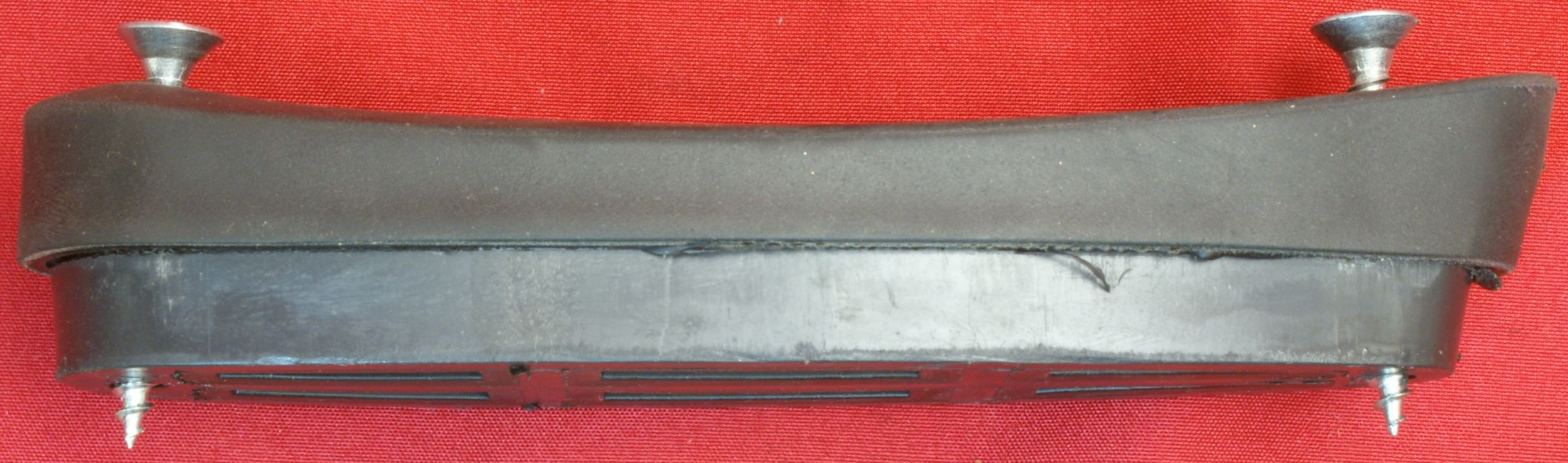
Figure 33
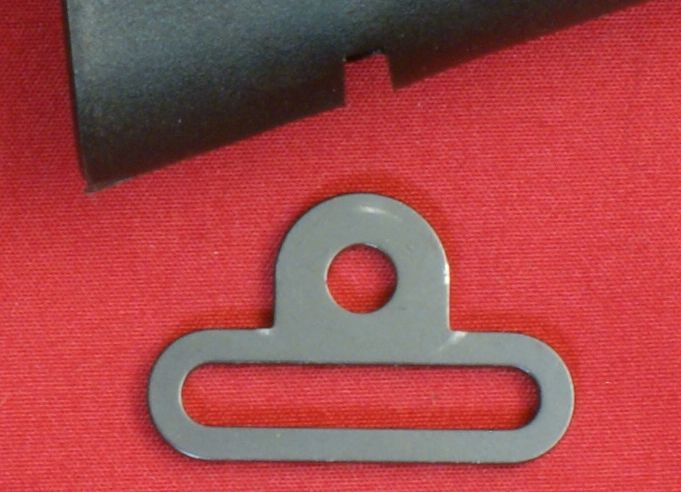
9 - Rear Sling Ring
The rear sling ring is made from steel and appears to be a stamped part. This ring slides in a slot in the bottom of the stock and is held in place with the lower buttpad screw.
Figure 34
Figure 35
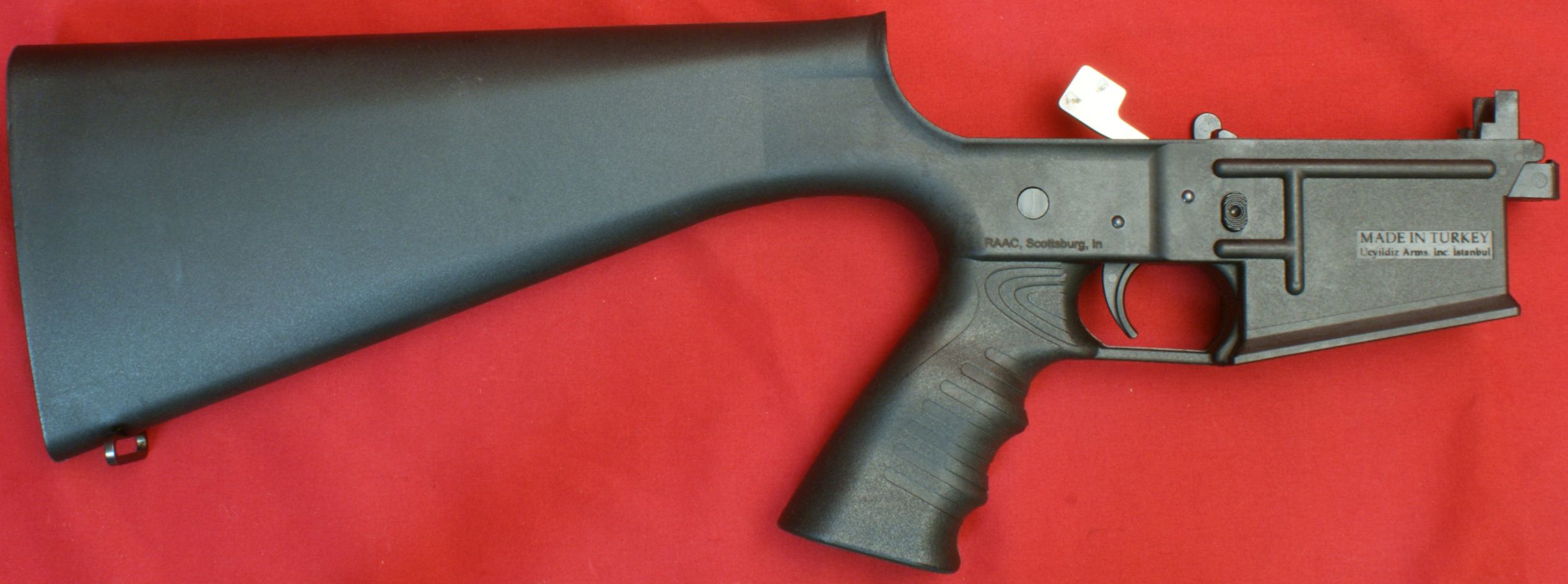
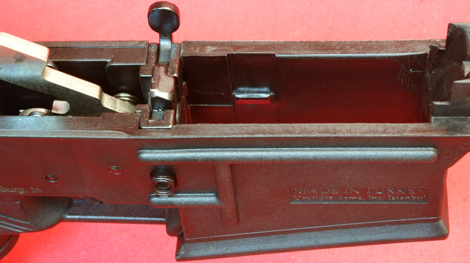
10 - Lower Receiver & Stock
The lower receiver, buttstock and pistol grip are one integrally molded polymer part. This assembly shown houses the safety selector, trigger/hammer, bolt catch and magazine catch.
Figure 36
These next couple of photos show overall views inside the lower receiver.
Figure 37
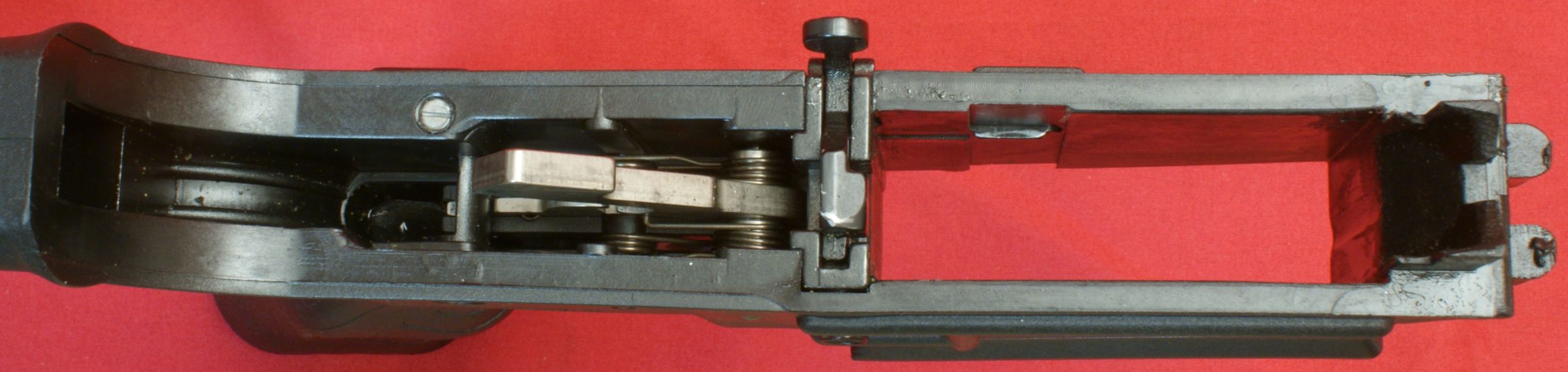
Figure 38
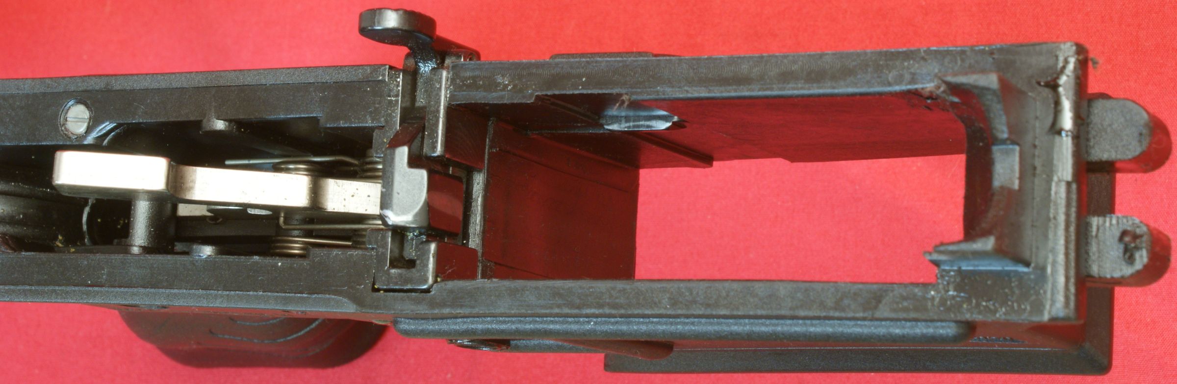
In the photo below you can see the portions of the lower receiver that mate with the front of the upper receiver. Even thought these portions are polymer material, based on their size, they should provide a long and durable life.
Figure 39
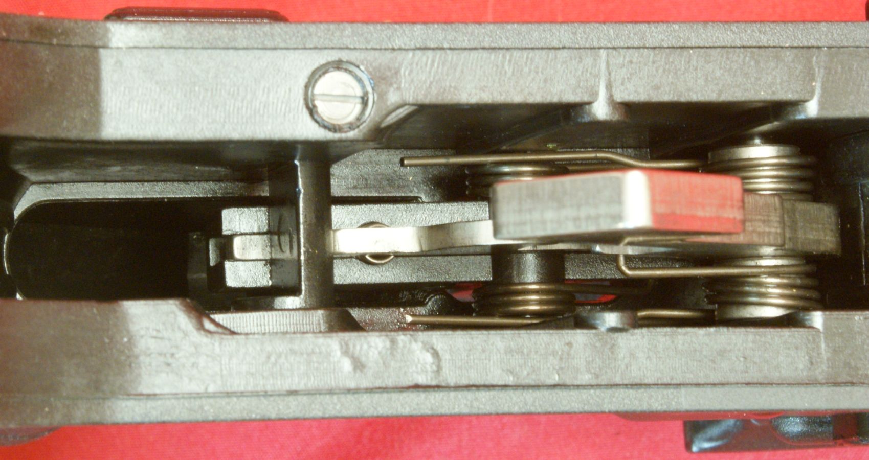
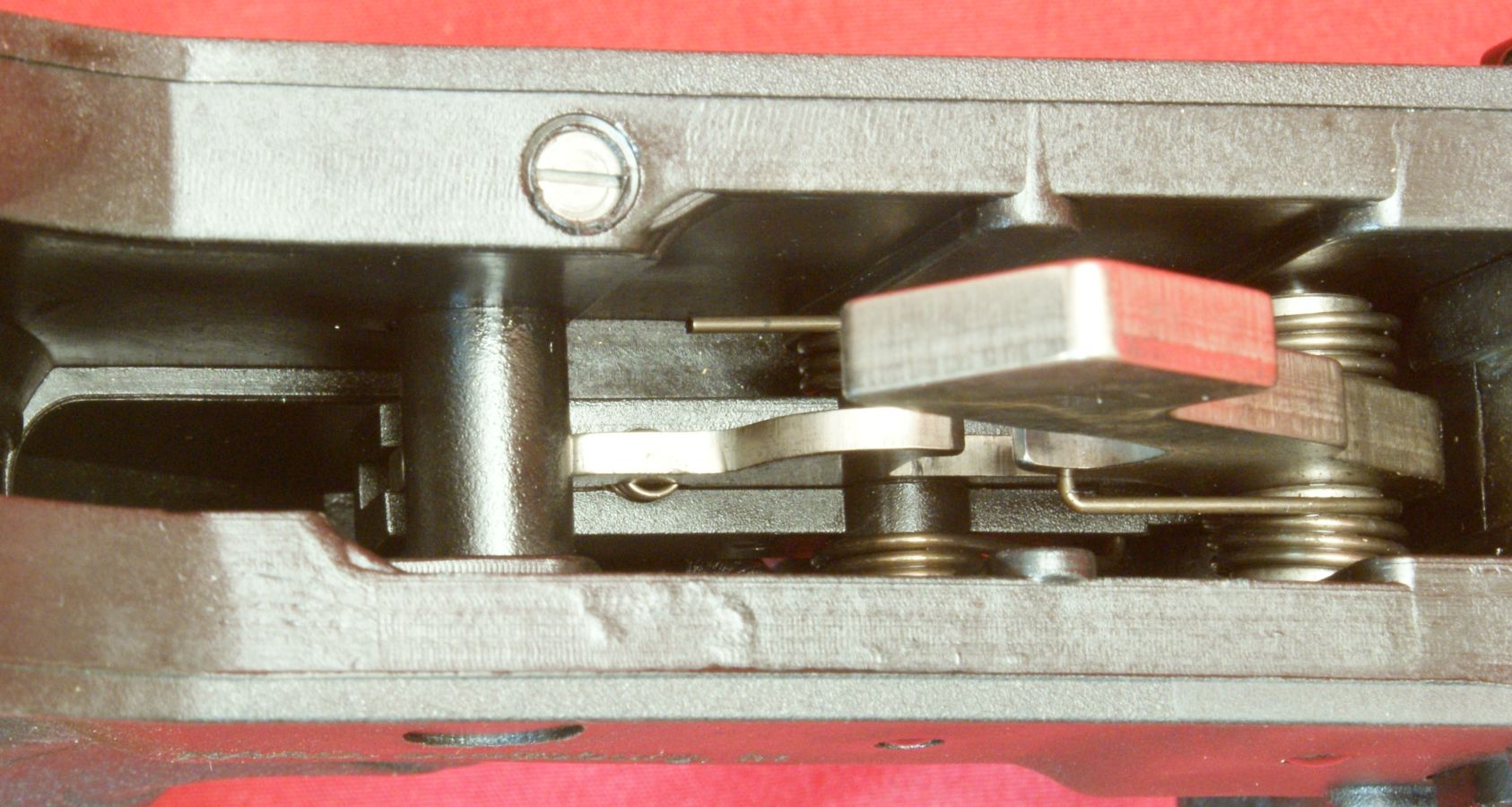
In the next two photos I have shown the safety selector switch in the "Safe" and "Fire" positions. You can see that the round portion of the switch is reduced to half thickness on one side only over the rear of the trigger/disconnector. When in the safe position, the round portion is positioned to be full thickness vertically so that you cannot move this portion of the trigger/disconnector up by pulling the trigger rearward.
Figure 40 - Safe Position
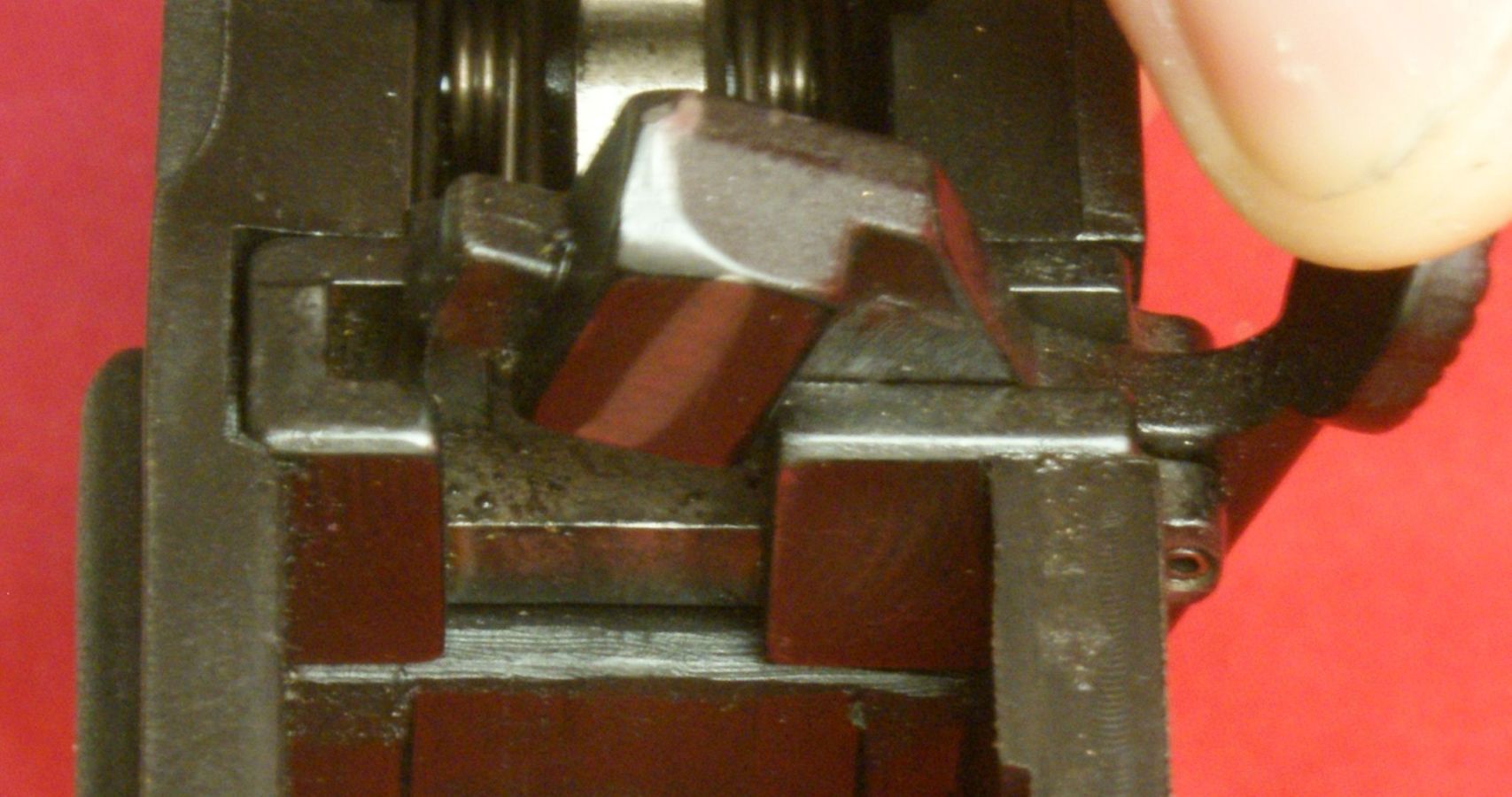
In the next photo the switch is in the "Fire" position and and the round portion has been rotated so that the rear of the trigger/disconnector can be moved up when the trigger is pulled.
Figure 41 - Fire Position
These next two photos show the bolt catch lever in the down and up positions. The up position will lock the bolt in it's rear position.
Figure 42
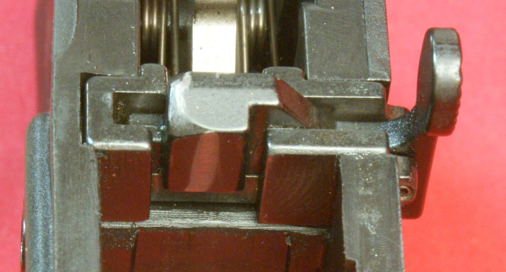
Figure 43
This next photo shows an empty magazine inserted in the lower receiver and you can see that this will push the bolt catch lever up so that it will lock the bolt open after the last round.
Figure 44
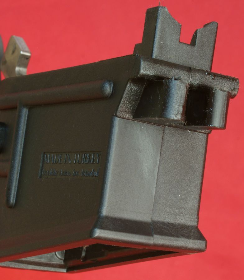
In this next photo I have tried to show the magazine release button and the catch on the far side of the magazine well.
Figure 45
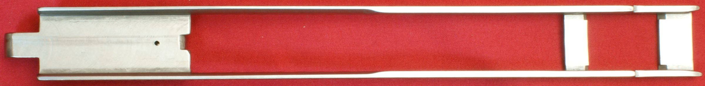
11 - Bolt Carrier
The bolt carrier (or action bar) is made from stainless steel and includes a spring loaded ball which holds the charging handle in place. The spring and ball appear to be held in place by staking (deforming) the carrier material on two sides of the ball.
Figure 46
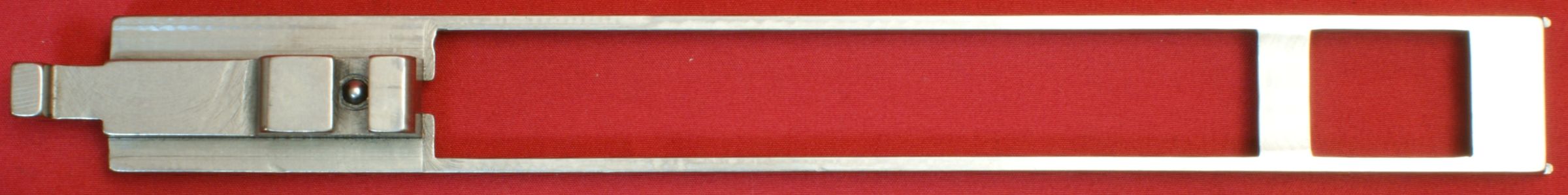
Figure 47

Figure 48
The front of the bolt carrier is held in place by a steel operating rod lug (action bar sleeve) shown below.
Figure 49
Figure 50
Figure 51
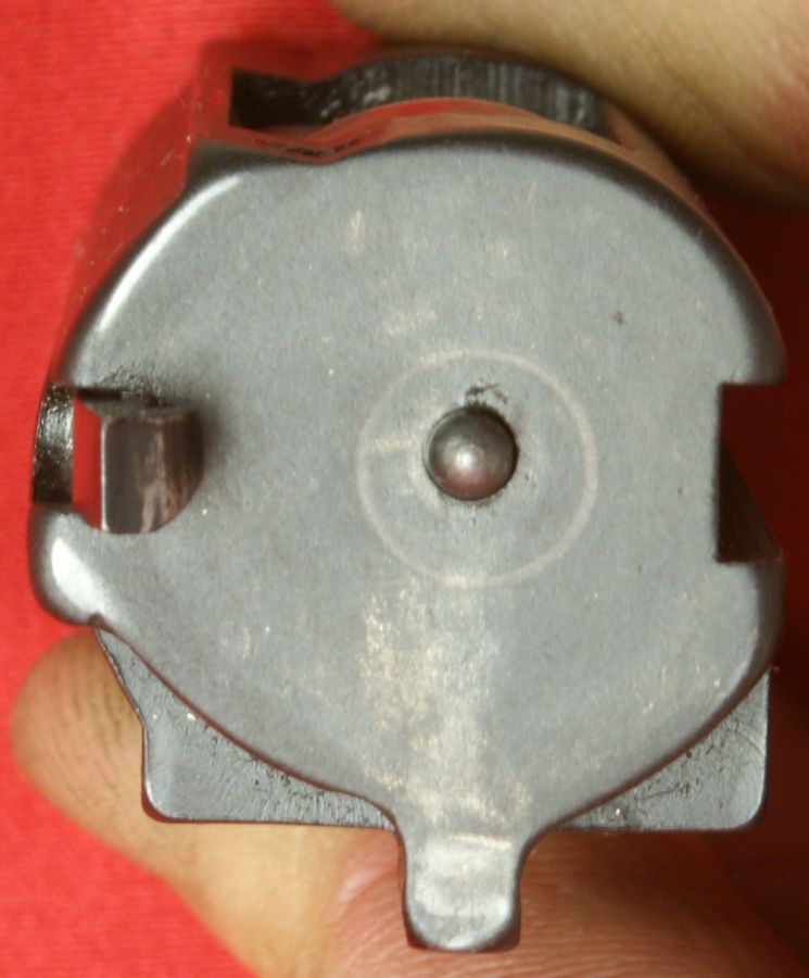
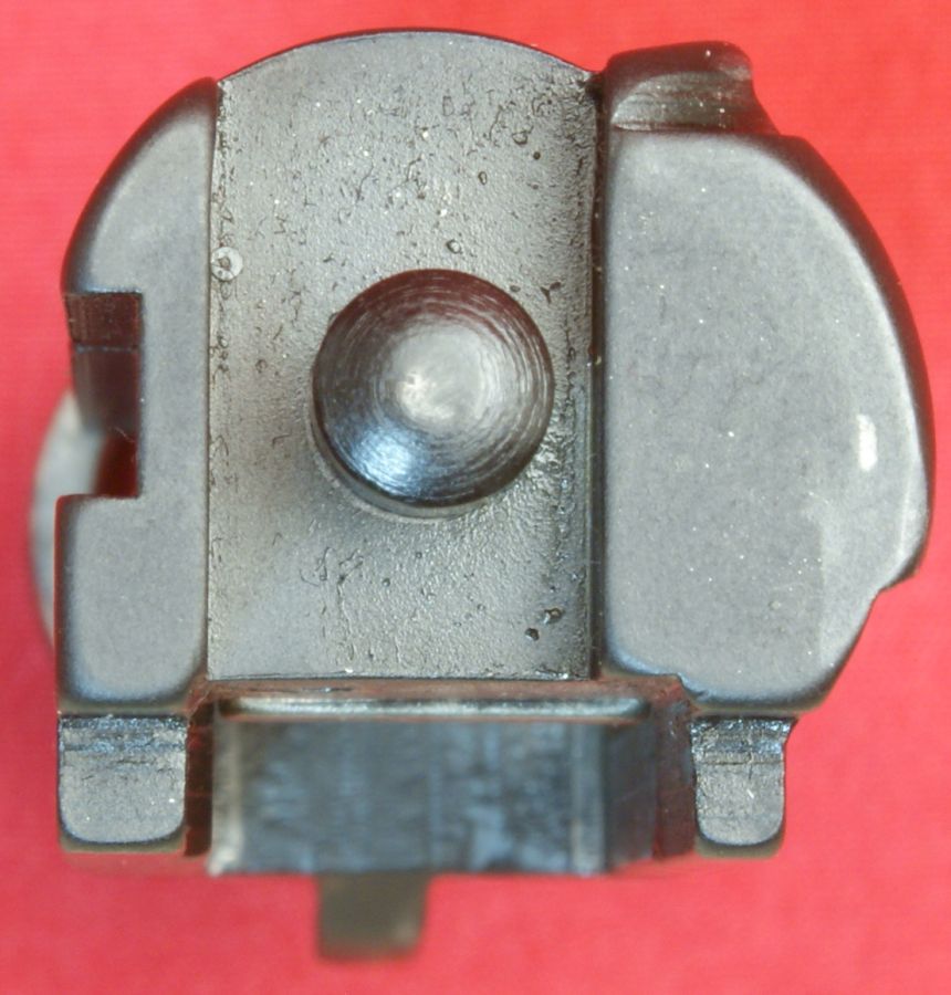
12 - Bolt
The bolt assembly is made from a combination of alloy steel and stainless steel parts. I was not able to locate any identifiable proof marks on the bolt. The bolt assembly is made up of breech bolt, locking block, firing pin & spring, and the extractor parts. The locking block appears to be made from stainless steel while the breech bolt from some type of alloy steel with a blued finish.
Figure 51
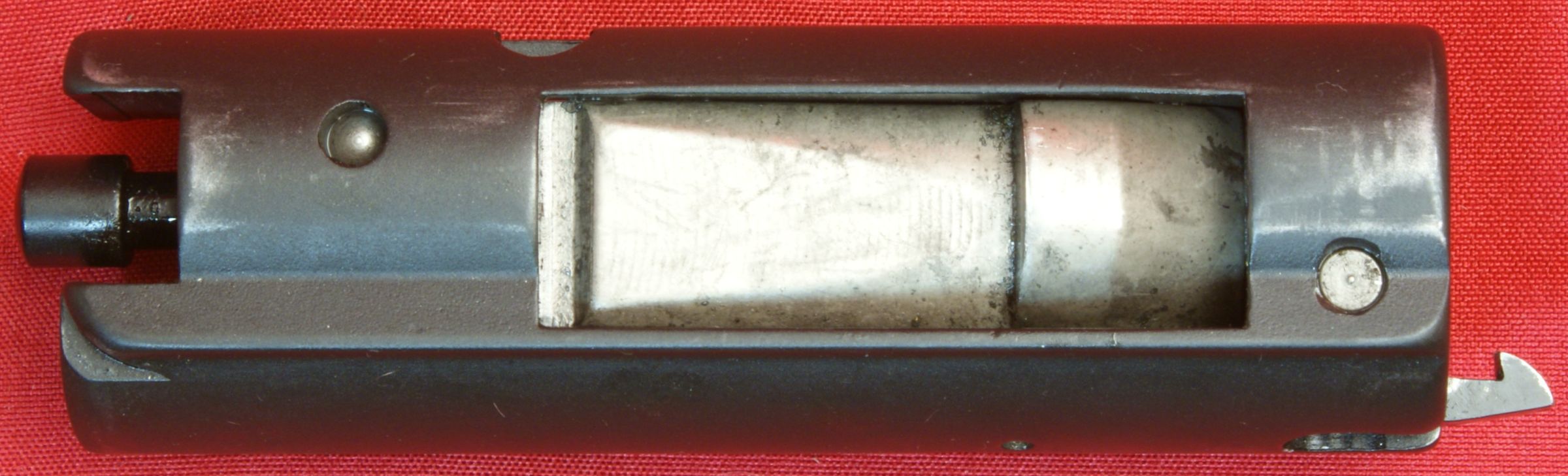
Figure 52
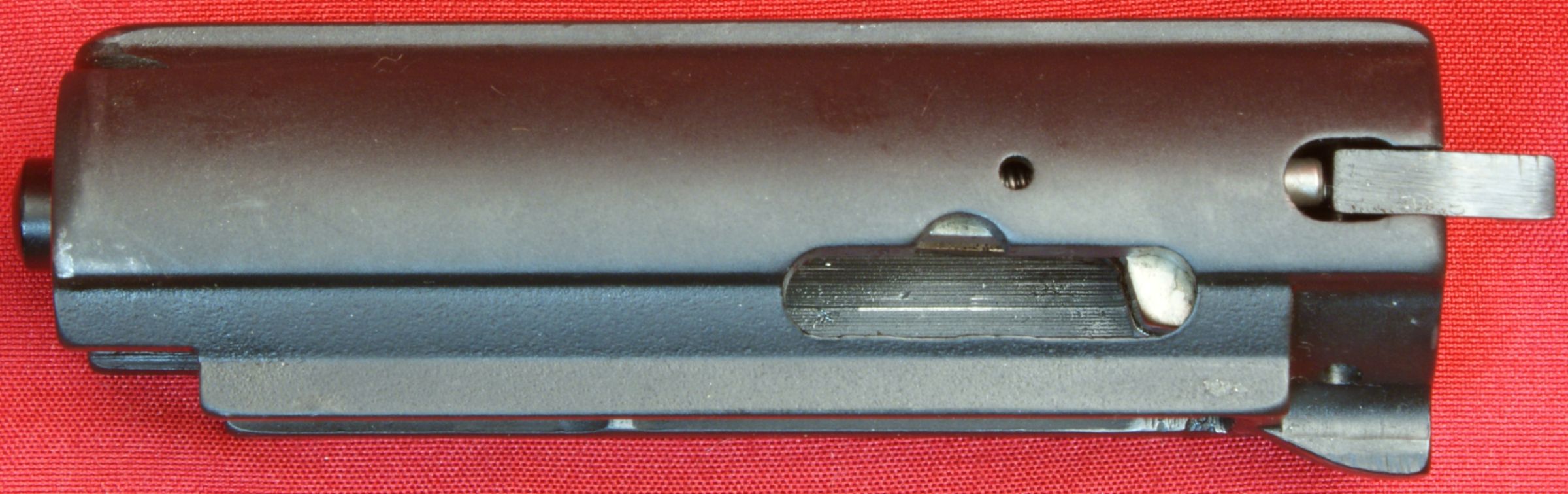
Figure 53
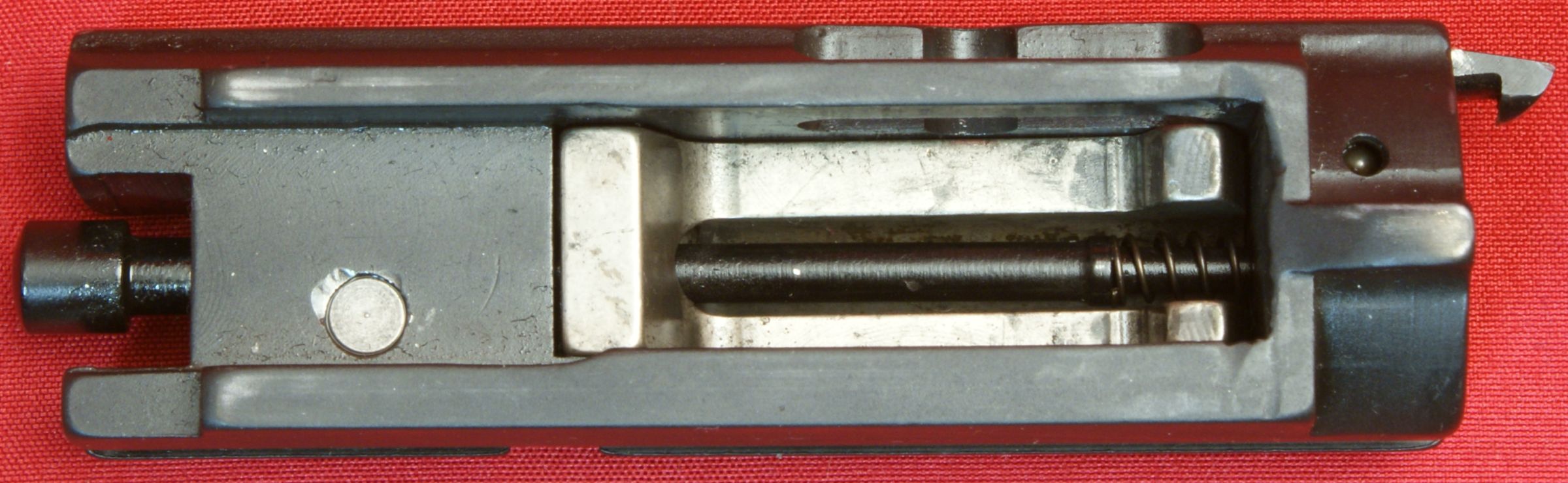
Figure 54
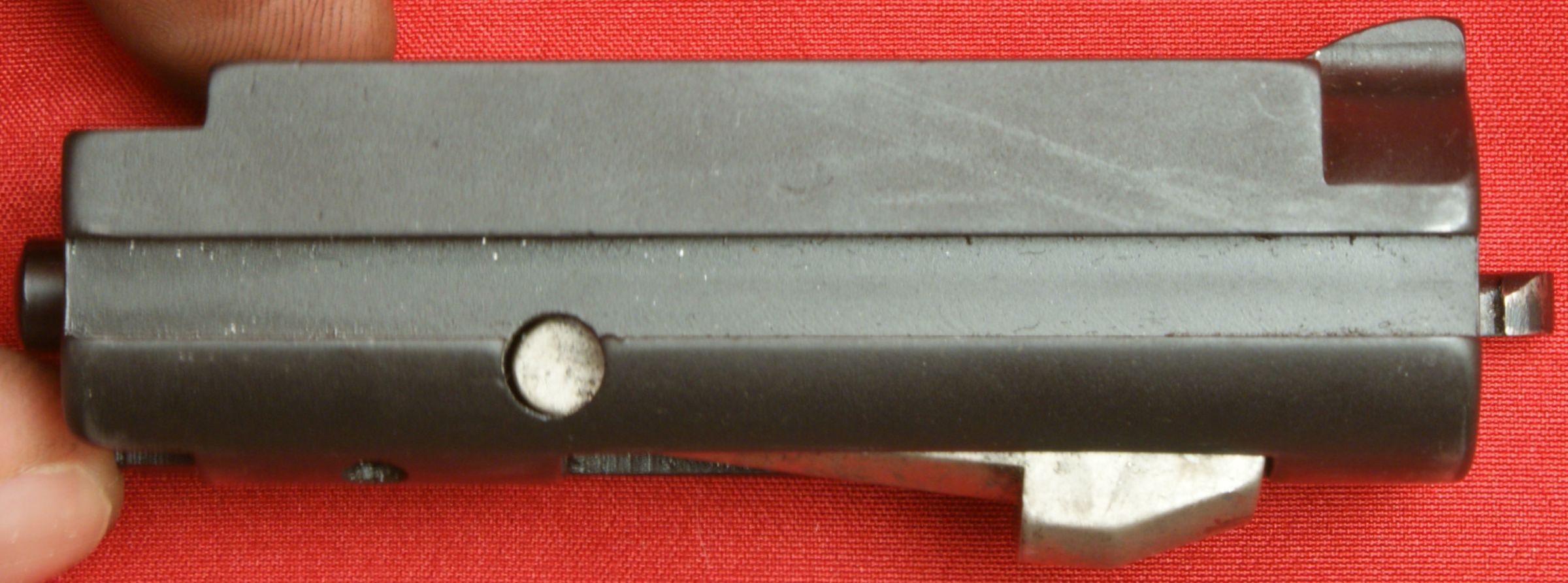
On the bottom of the breech bolt is an extension/lug that is used to strip the next round from the magazine and is also used to lock the bolt open after the last shot if fired.
Figure 55
Figure 56
The charging handle is made from steel and includes a notch (if needed) for removing the handle from the bolt.
Figure 57
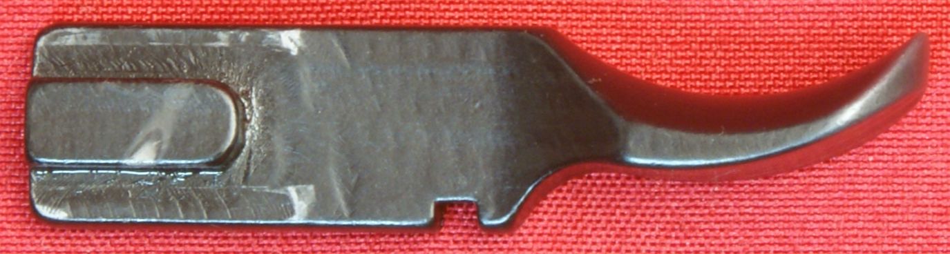
Figure 58
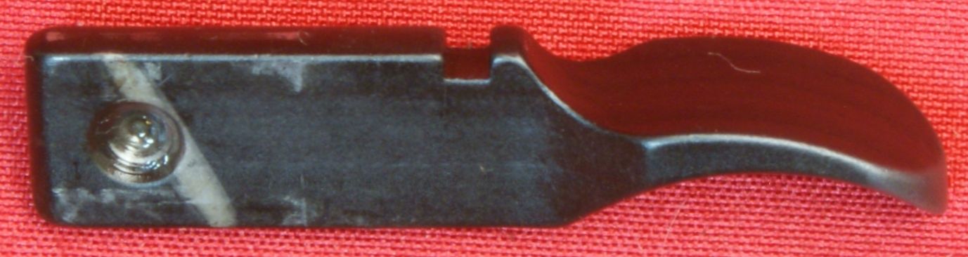
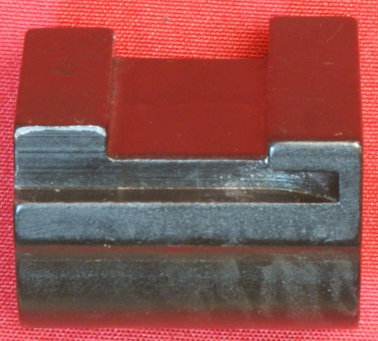
13 - Rear Handguard Secure Plate
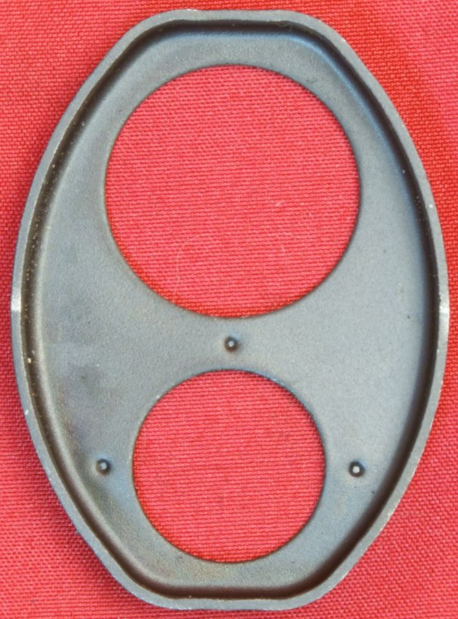
The rear handguard secure plate appears to be a stamped formed steel part. This plate is held in place by the operating rod and there was no freeplay in this assembly.
Figure 59
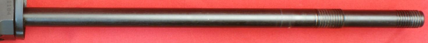
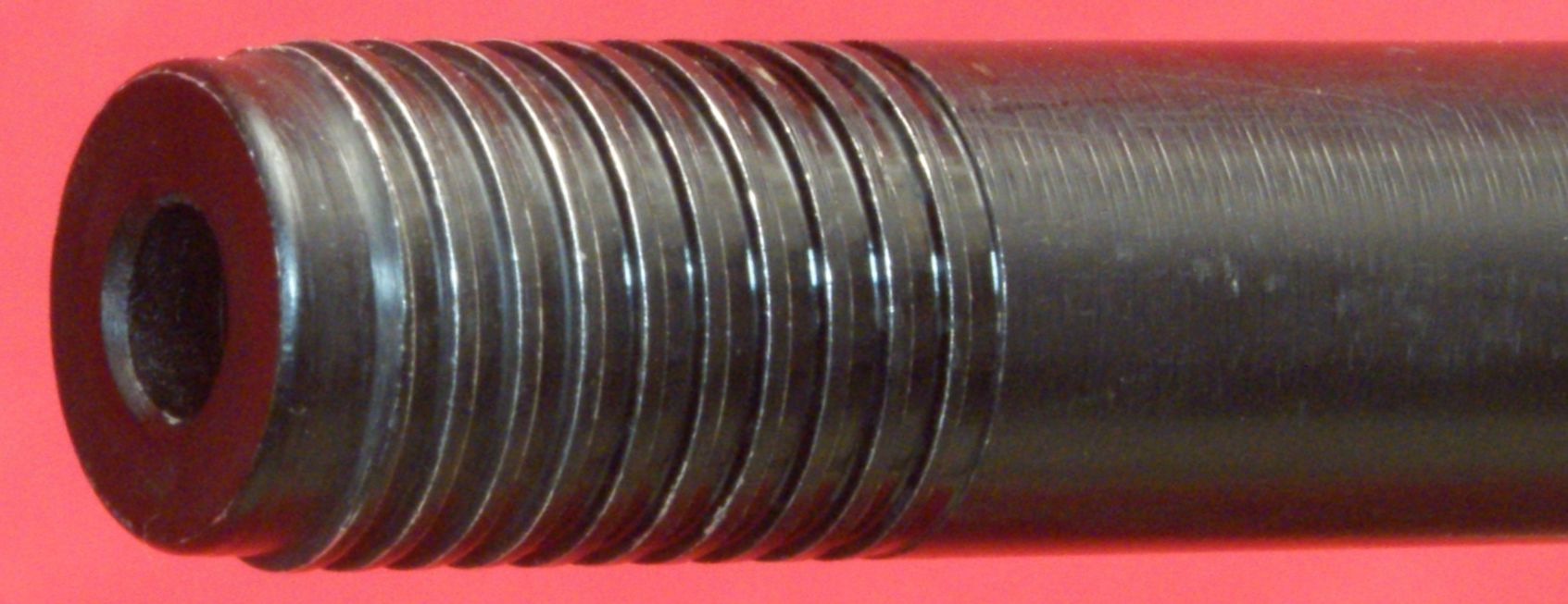
14 - Operational Rod
The operating rod is an aluminum solid rod that measures about 13.35" in length and is 0.625" in diameter in the area for the bolt carrier lug and gas pistol.
Figure 60
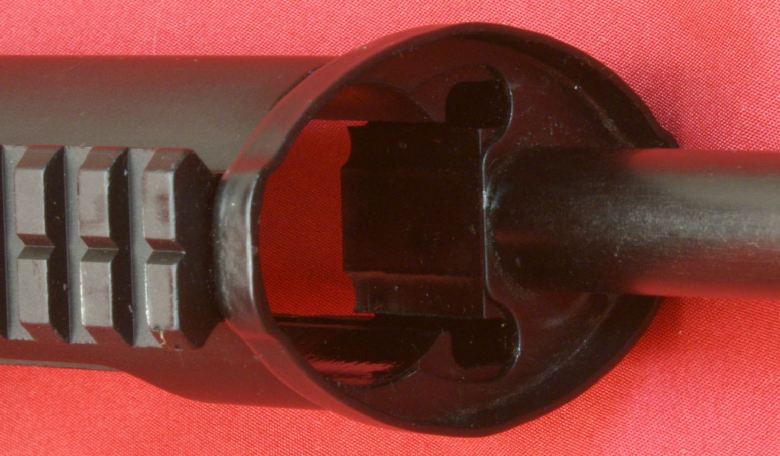
The end of the rod makes it appear to be hollow, but this hollow area only goes about 1.18" deep.
Figure 61
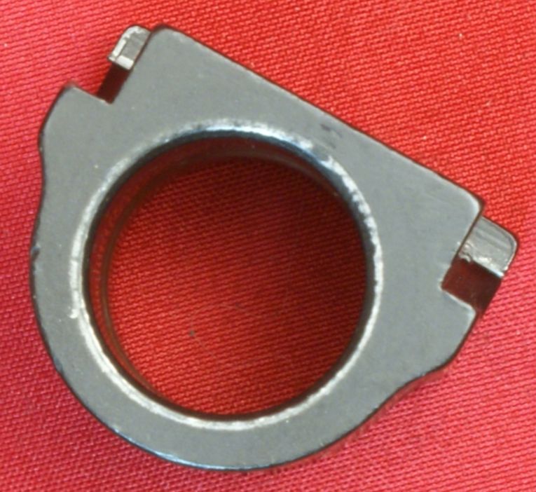
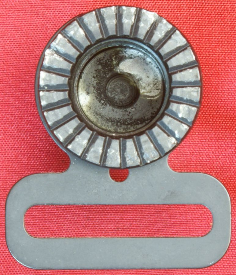
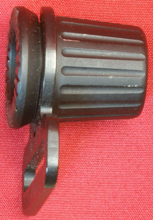
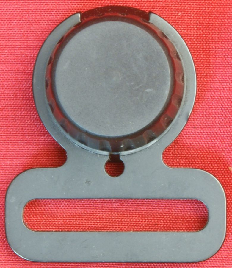
15 - Front Sling Ring & 20 - Handguard Secure Cap
The front sling ring is made from steel and the handguard secure cap is made from aluminum. The bottom of the cap has grooves to engage with a protrusion on the font handguard secure plate to help in preventing this cap from working loose.
Figure 62
Figure 63
Figure 64
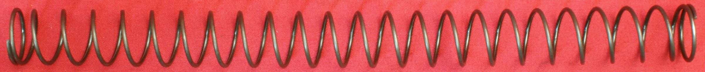
16 - Recoil Spring
The recoil spring is made from steel and measures about 8.6" uncompressed and has an outside diameter of about 3/4".
Figure 65
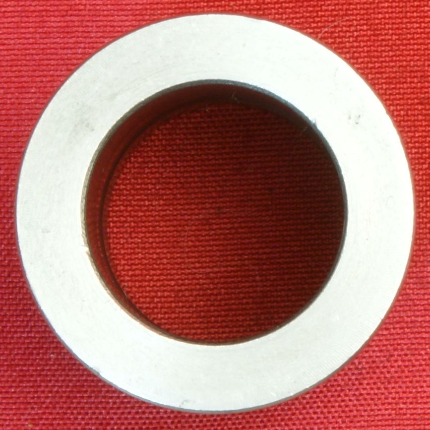
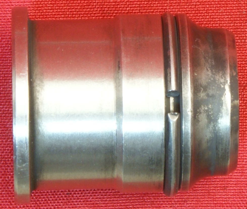
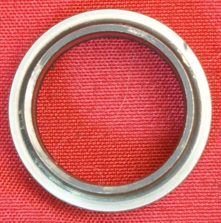
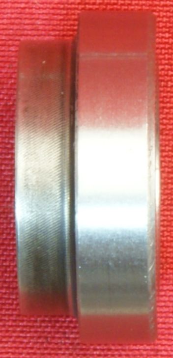
17 - Gas Piston
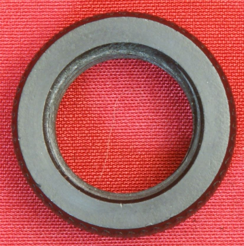
The gas piston is not magnetic but seems to be too heavy to be made from aluminum, there fore I believe it is made from some other 3xx (i.e. 316) stainless steel. The gas piston has a steel ring which acts as a gas seal inside the barrel lug chamber.
Figure 66
Figure 67
Figure 68
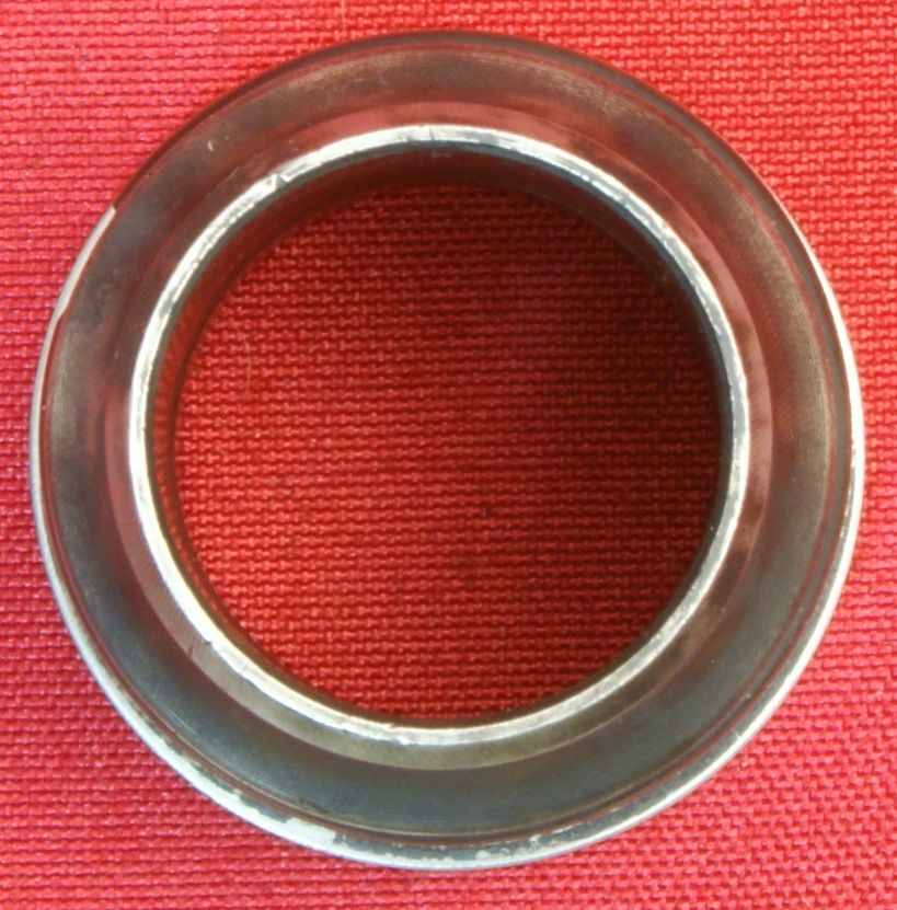
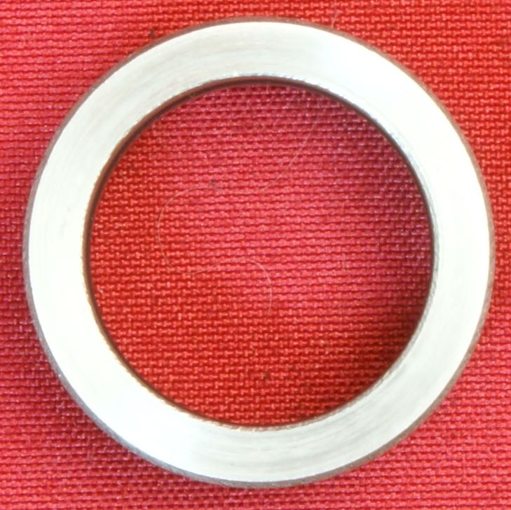
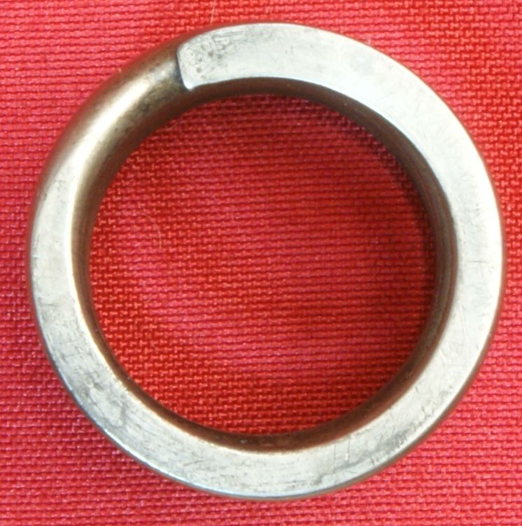
On the front side of the barrel lug is another stainless steel ring which has an O-ring on the inside. This ring presses against the gas regulator spring and somehow allows gas to vent forward.
Figure 69
Figure 70
Figure 71
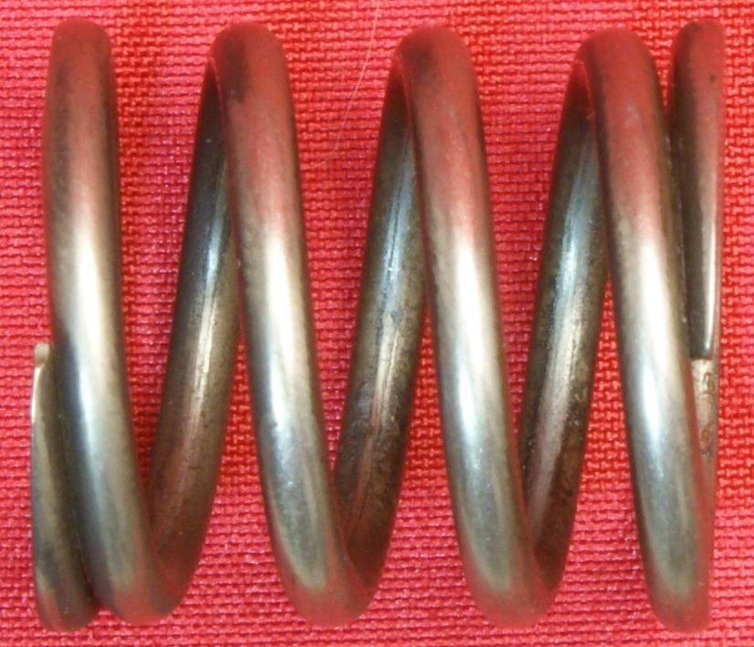
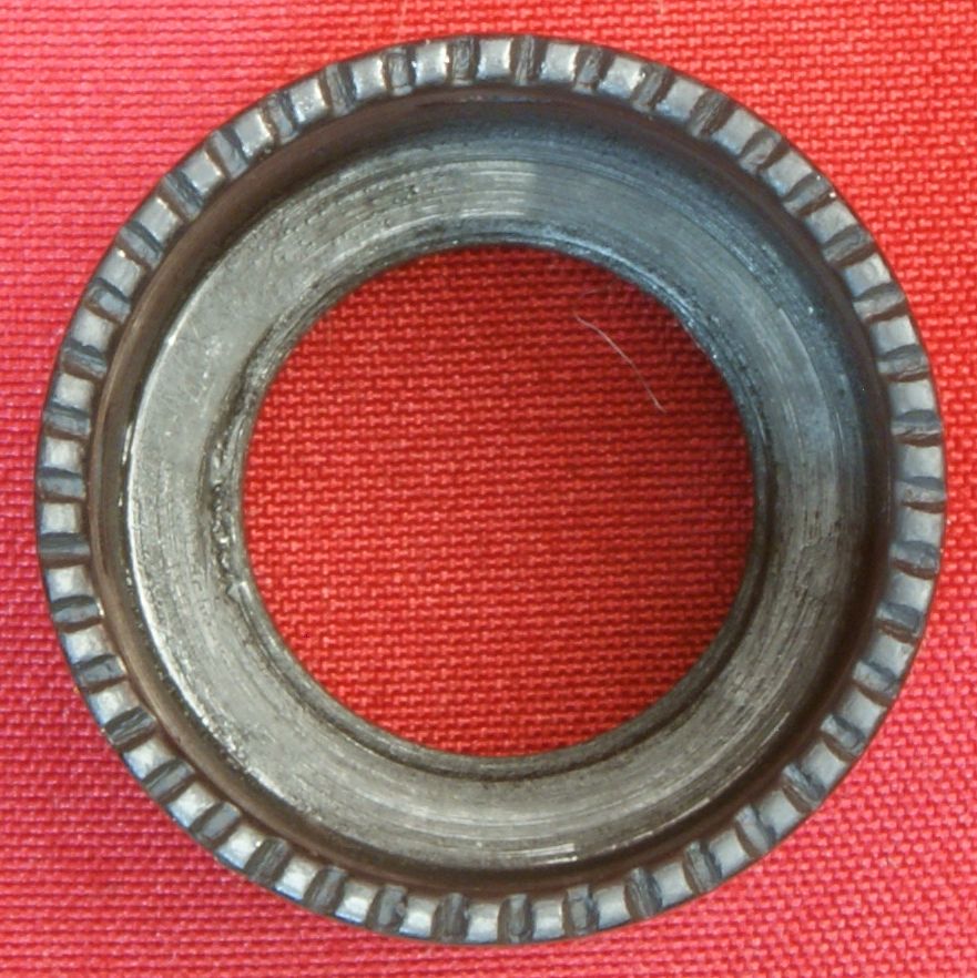
18 - Gas Regulator Nut/Spring
The steel gas regulator spring measures 8.875" in length and about 0.85" in diameter.
Figure 72
Figure 73
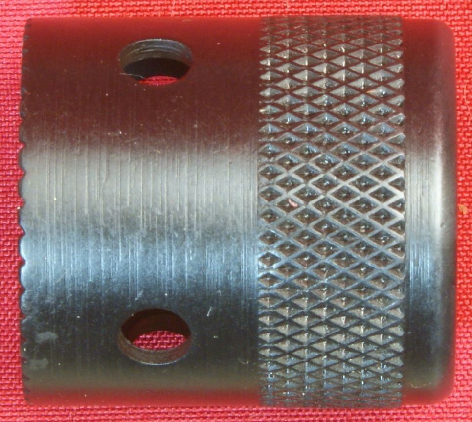
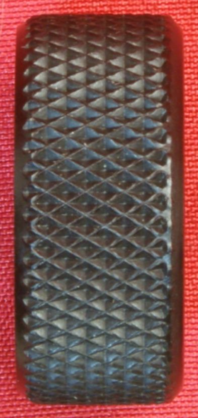
The gas regulator nut is also made from steel and measures 1.10" in length. This nut has 4 vent holes and a knurled area for hand tightening.
Figure 74
Figure 75
Figure 76
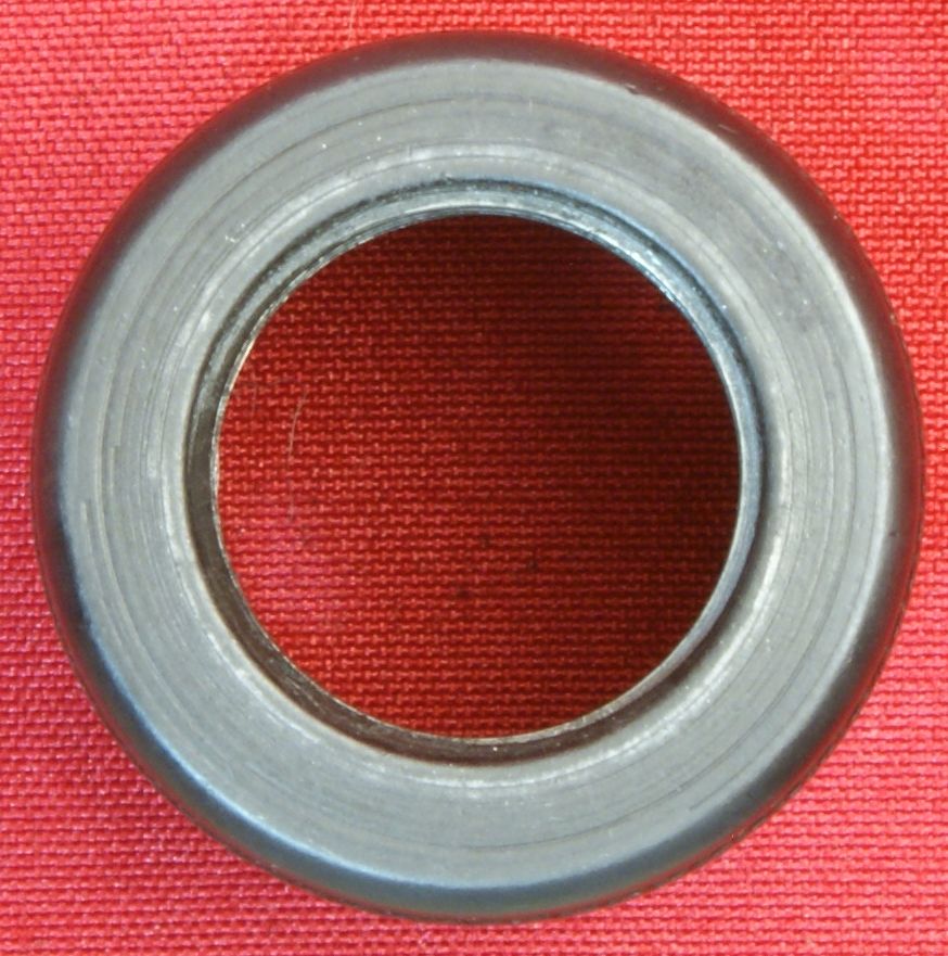
The gas regulator nut also has an aluminum lock nut that is tightened against the gas regulator nut to help prevent the gas regulator nut from working loose. During all my range tests, I found that the gas regulator would still work loose.
Figure 77
Figure 78
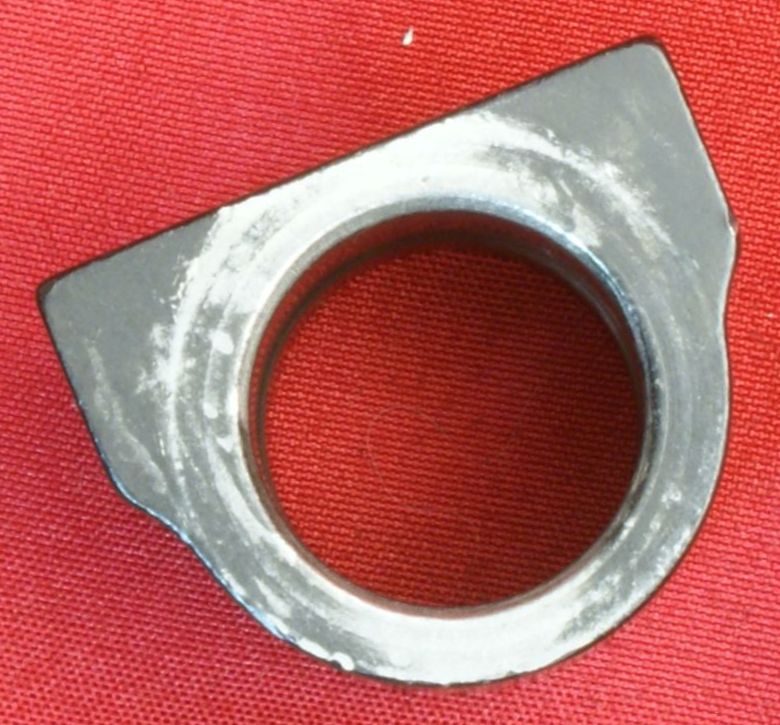
19 - Front Handguard Secure Plate
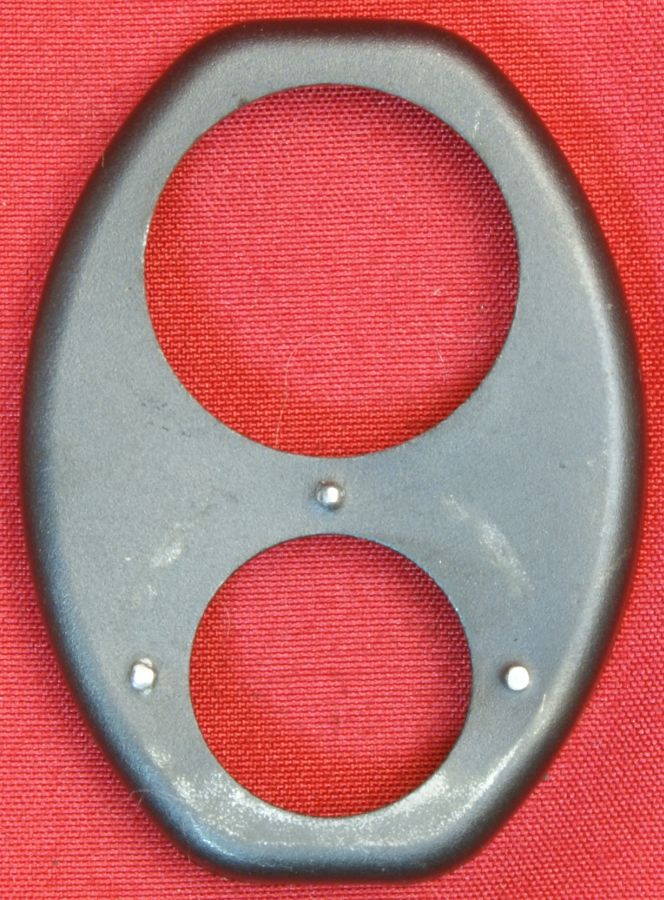
The front handguard secure plate is a stamped steel plate with blued finish. This plate includes three raised bumps to help prevent the handguard secure cap from working loose. Also during my range tests I found that the cap would still work loose.
Figure 79
Figure 80
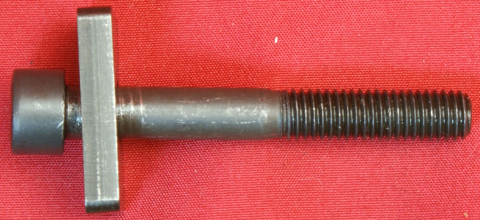
21 - Upper Receiver Retention Bolt/Washer
The upper receiver retention bolt and washer are both made from steel. The head markings on the bolt indicate that it is a metric grade 8.8 which is basically a standard grade 5 bolt. The bolt is 8mm in diameter and 60mm in length.
Figure 81
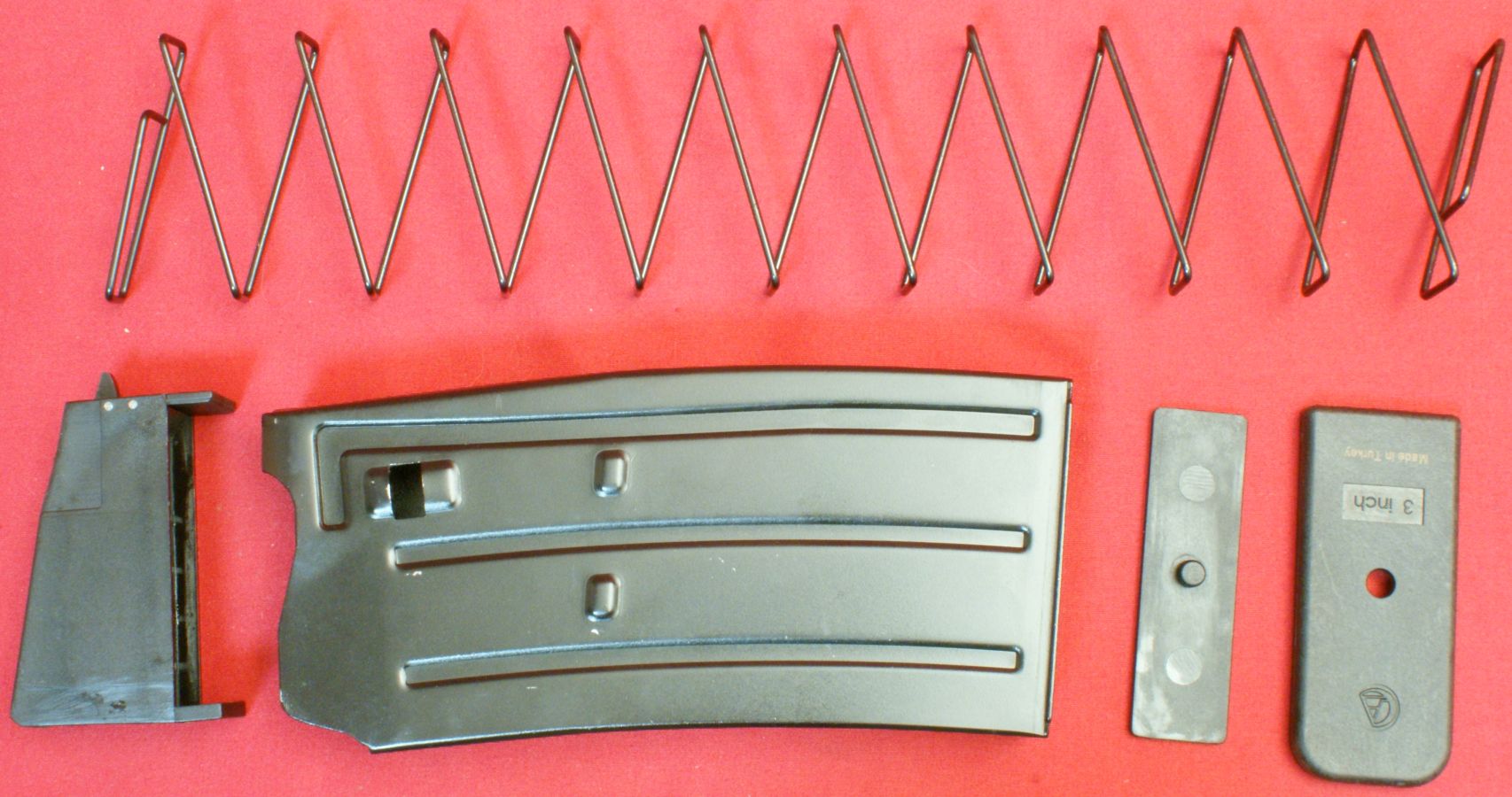
22 - Magazines
The 5 round magazine has a steel body, steel spring, and polymer follower, spring seat and floor plate.
Figure 82
Thoughts
Even though I have nit-picked a few items, overall I have a positive impression for the internal features of the MKA 1919 Shotgun. In my view, this is a very simple shotgun design and I wonder why someone else hasn't already thought of this concept (AR platform concept based on normal shotgun style gas operated system). I believe there are opportunities for improvement with one being to add a steel insert into the back of the upper receiver for the receiver retention bolt. In my detailed examination of the upper receiver, I did find an area that is clearly getting excessive wear due to the locking block pressing against the upper surface of the aluminum receiver. Is this a real problem? That is hard to say without extensive range testing. Therefore I cover the progression of this wear in my next part of the review where I cover range testing.
For more detailed photos and commentary, make sure you check out the other parts of this review and feel free to leave comments on my Reader's Comments page or below. The following links are provided to help you see other parts of this review.
- MKA 1919 Shotgun Review: Part 1 - Introduction, Specifications and Summary
- MKA 1919 Shotgun Review: Part 2 - What's in the Box
- MKA 1919 Shotgun Review: Part 3 - External and Operational Features
- MKA 1919 Shotgun Review: Part 4 - Disassembly
- MKA 1919 Shotgun Review: Part 5 - Internal Features (this page)
- MKA 1919 Shotgun Review: Part 6 - Range Test
- MKA 1919 Shotgun Review: Part 7 - Flash Suppressor & High Capacity Magazine Legal
- MKA 1919 Shotgun Review: Reader's Comments
Or
If you would like to be notified about future Gunsumer Reports reviews via Facebook, make sure "You Like This" by clicking the Facebook "Like" button at the bottom or top of this page. If it already says "You Like This" beside the button, clicking it again will uncheck the "Like" status and you will not be notified.
| Share on Facebook | |
© 2010, 2011, 2012, 2013, 2014, 2015, 2016, 2017, 2018, 2019, 2020, 2021, 2022, 2023 & 2024 Gunsumer Reports™, All rights reserved.
FTC Disclosure