|
|
Gunsumer Reports TM Providing Detailed Objective Reviews for Firearms and Firearm Accessories |
Remington 700 SPS Tactical AAC-SD
Review
Part 4 - Disassembly and Internal Features
January 1, 2012
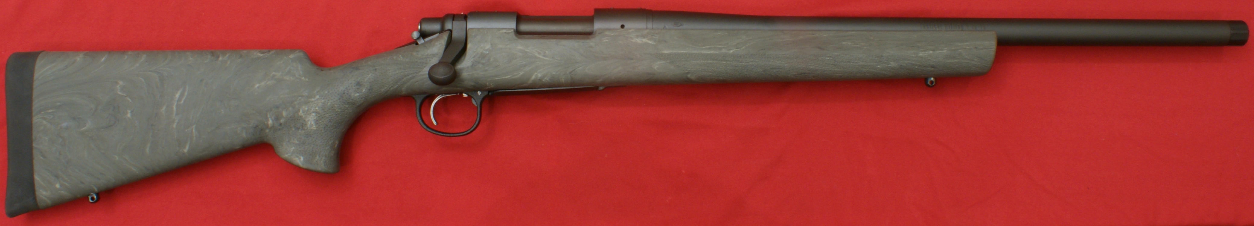
In Part 3 of my Remington 700 SPS Tactical Review, I covered in great detail the external features of the AAC-SD version of this rifle. In this part of the review, I'm going to show the basic disassembly of the rifle and discuss some of the internal features. Generally speaking, I will follow the steps outlined in the Owner's Manual for disassembly and you should always consider the Owner's Manual as the primary source for any information relating to the operation and safety of your firearm.
Disassembly
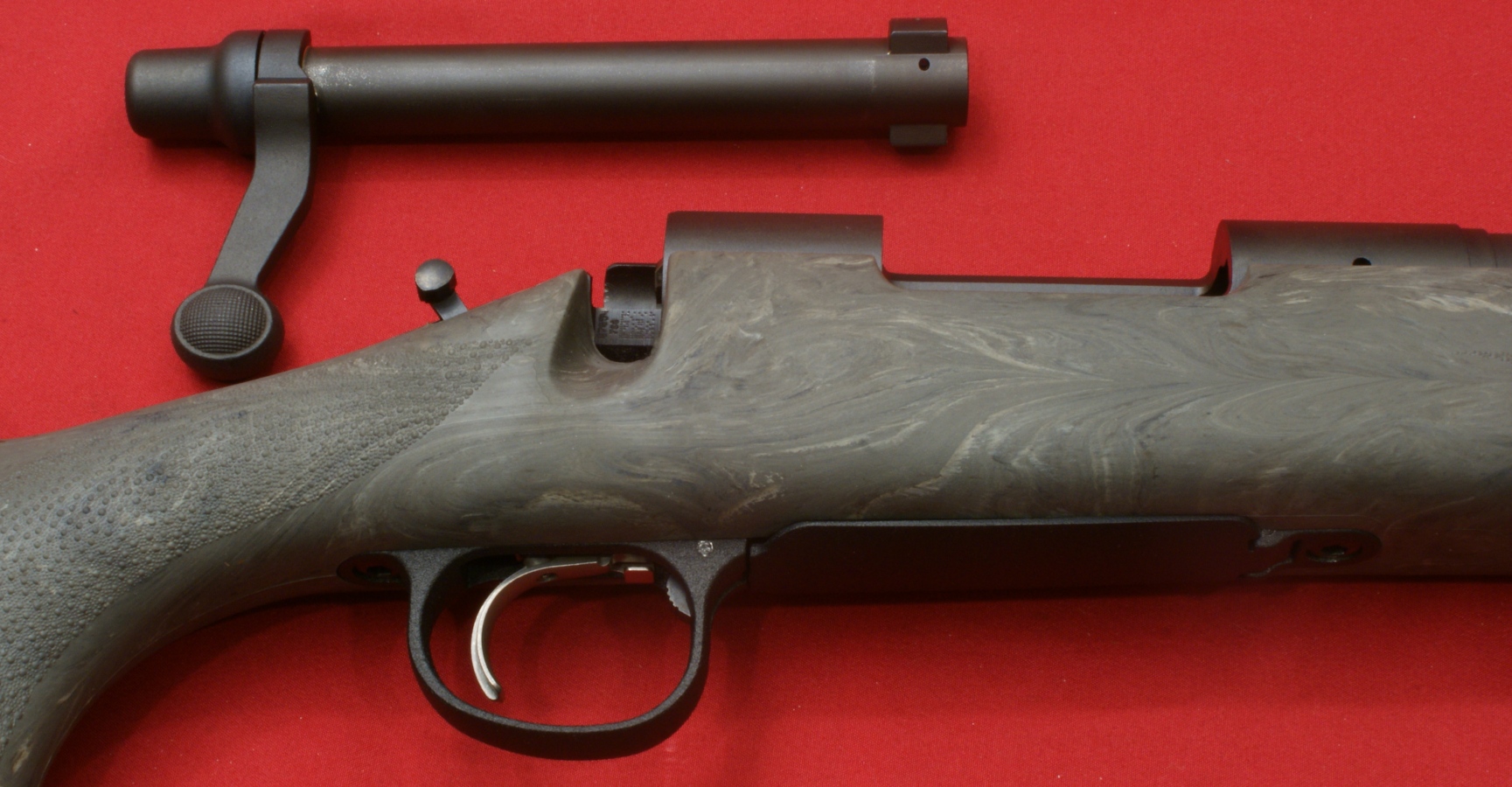
Step 1 - Bolt Removal
Always make sure the firearm is unloaded, pointed in a safe direction and the safety mechanism is in the "S" position. Raise the bolt handle and pull the handle all the way back while pressing on the bolt stop release. The bolt will easily slide out of the receiver.
Figure 1
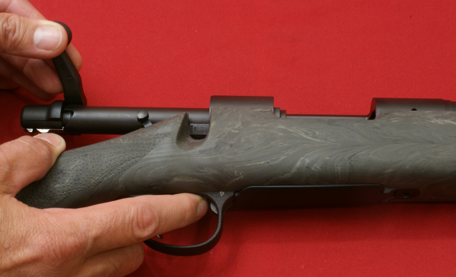
Figure 2
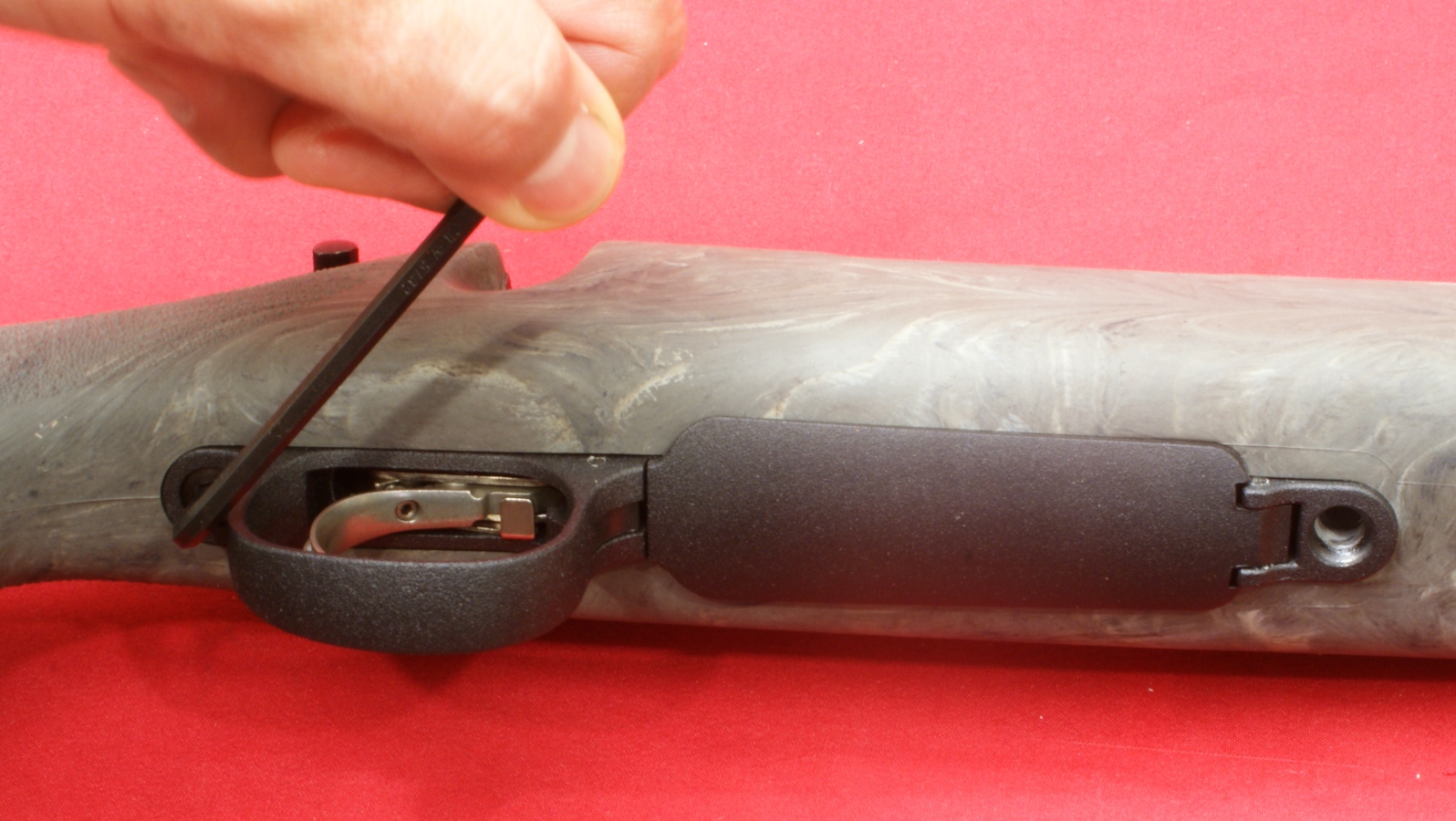
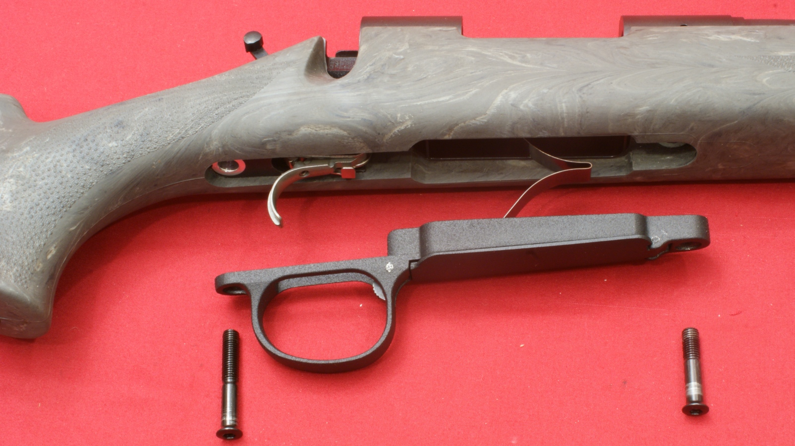
Step 2 - Remove Trigger Guard Assembly
Using an Allen Wrench, remove the two stock screws in the front and rear of the trigger guard assembly.
Figure 3

Figure 4
The trigger guard assembly will slide out of the stock. The trigger guard assembly was a snug fit (a good thing) inside the Hogue stock but it was not too hard to take out.
Figure 5
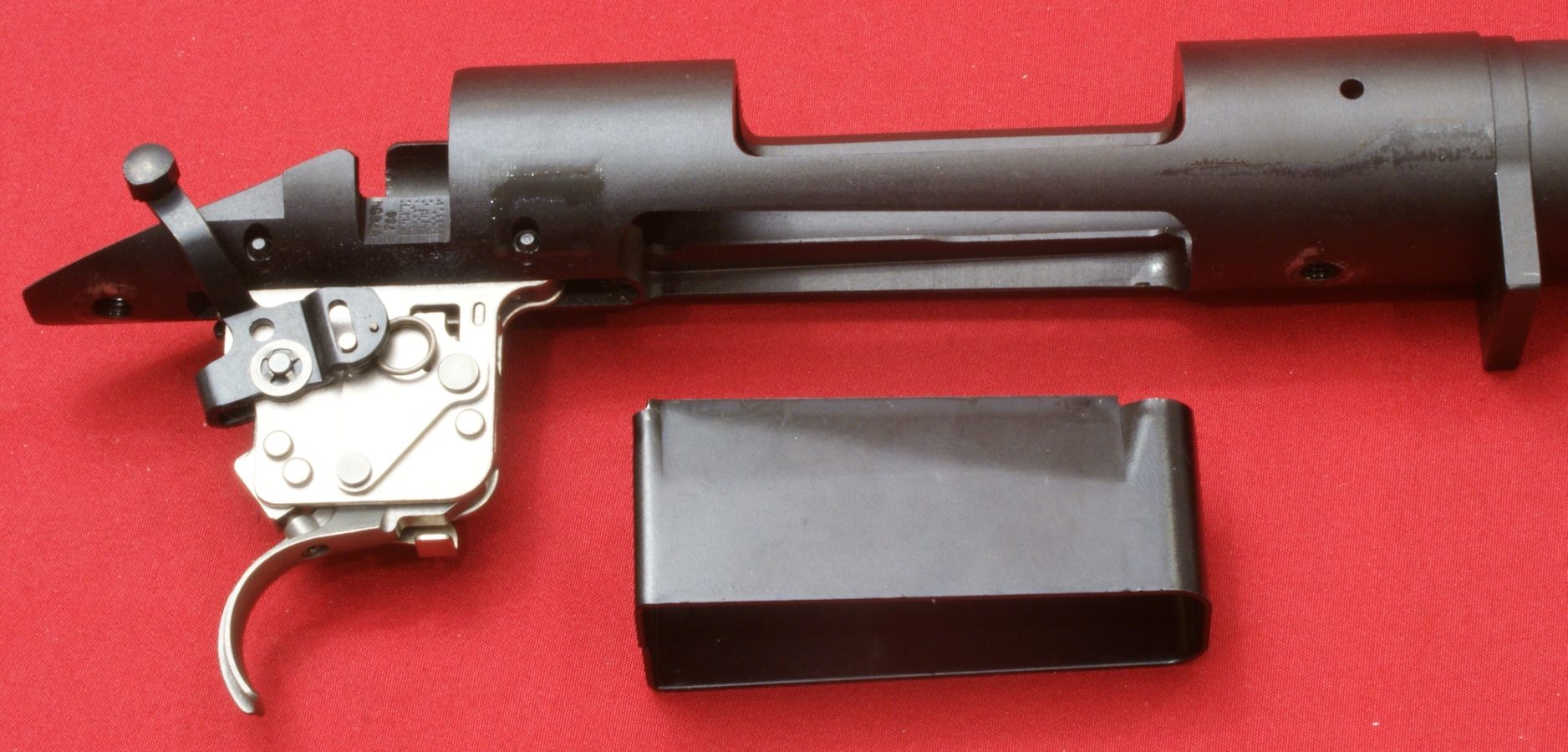
Step 3 - Remove Receiver & Barrel
The receiver and barrel assembly easily lifted up and out of the stock. When mine came out, the magazine stayed inside the receiver as seen below.
Figure 6

The magazine separated from the receiver by pulling it down from the receiver.
Figure 7
Although not an official step in disassembly, I decided to go ahead and show a photo with the thread protector removed.
Figure 8

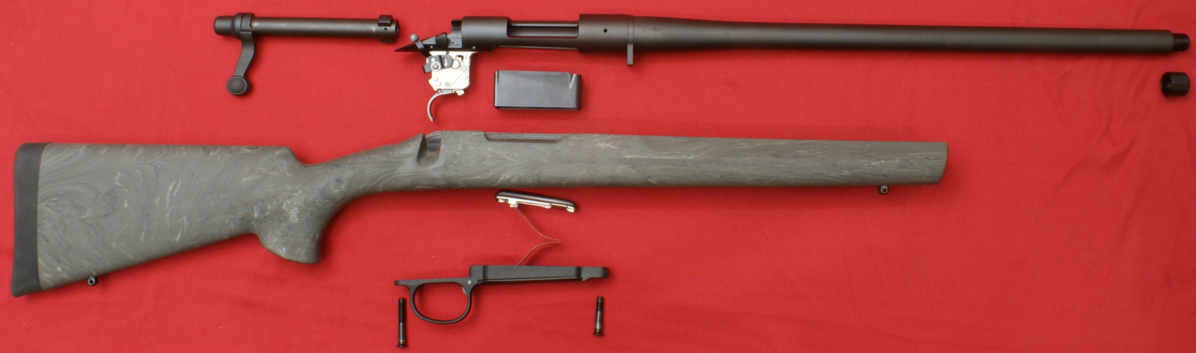
In most cases, this will most likely be as far as you will disassemble the rifle during normal cleaning of your rifle.
Figure 9
Bolt Disassembly
I decided to go ahead and show the steps for removing the firing pin assembly from your bolt. With the bolt removed from your rifle, I placed the blade of a screwdriver in the notch on the firing pin head.
Figure 10

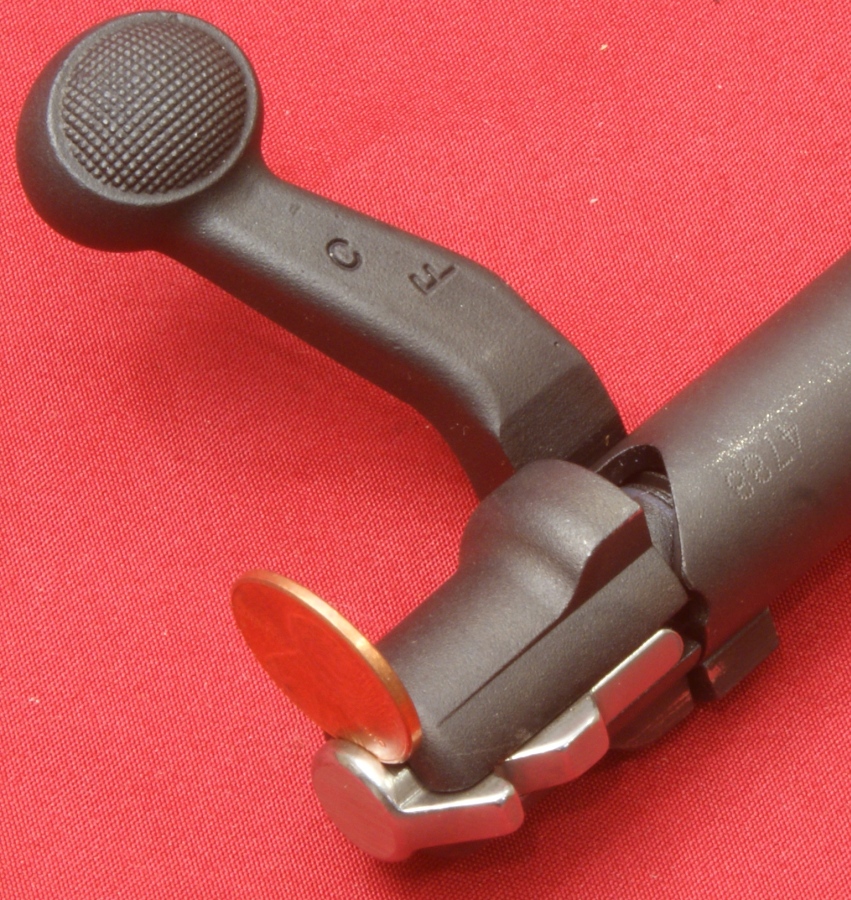
While holding the bolt, I was able to pull the firing pin head rearward to reveal the notch in the firing pin head.
Figure 11

With my third hand (my son), I placed a penny in the notch. The Owner's Manual shows you doing this using a bench vise that is holding a piece of metal to put in the notch like the screw driver I used. I believe using the Owner's Manual technique would have allowed a single person to do this task.
Figure 12

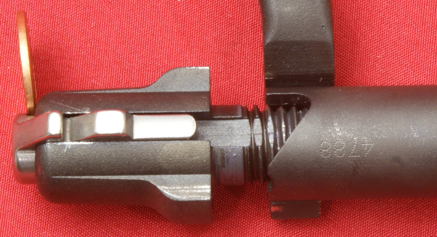
The coin will hold the firing pin so that it is no longer spring loaded against the bolt.
Figure 13
You can then unscrew the firing pin assembly from the bolt.
Figure 14
The firing pin can then be removed from the bolt as shown below.
Figure 15
Internal Features
Since many of the features of Remington 700 SPS Tactical AAC-SD can be seen externally, I may only mention items which I covered in detail Part 3 of the review. Instead I will focus on those items which I feel the average person may not realize when disassembling the rifle. I will also show many photos so that you can examine the internal features yourself so you can form your own opinions.
Receiver
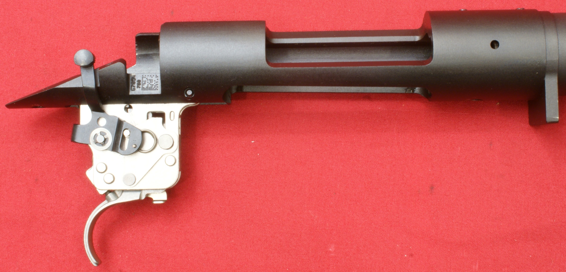
The receiver is machined from a round billet of high strength steel and is about 1.360" in diameter. The four holes drilled and tapped into the receiver for mounting a scope pass through the full thickness of the upper wall of the receiver.
Figure 16
The gas vent hole in the right side of the receiver is to allow hot gasses to pass out of the chamber in the event there was some type of issue like a case rupture when firing the rifle. Between the barrel and receiver is the recoil lug. Since the receiver and recoil lug are two separate parts, both parts are easier to machine and this also reduces fabrication costs by reducing the total material needed to be removed during the machining process.
Figure 17
The bottom of the receiver is recessed around the magazine so that the magazine fits securely in the correct location in the receiver. You can see the two threaded holes at the front and rear of the receiver for the stock bolts. Also notice the shiny areas around the holes. This is where the aluminum bedding pillars are making solid contact against the bottom of the receiver.
Figure 18
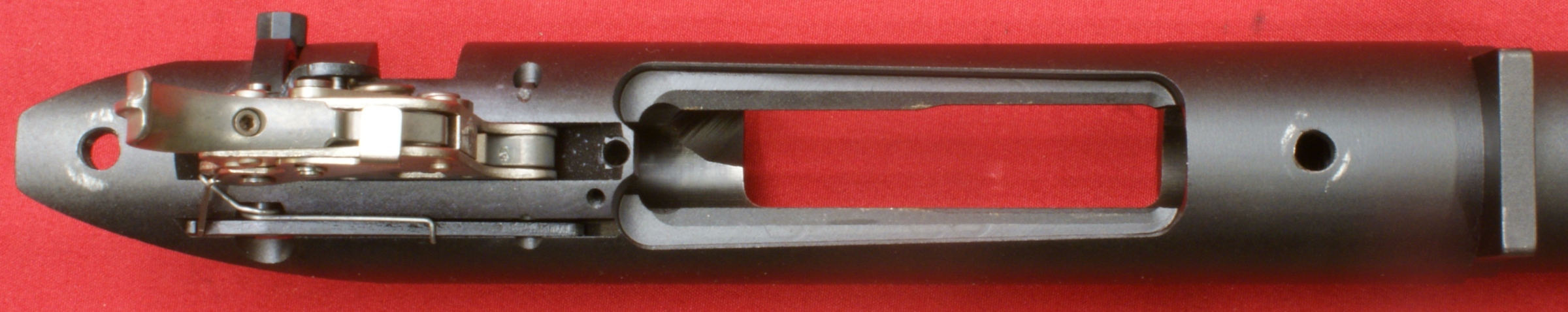
The trigger assembly is pinned in place with two pins (photo below). In the photo above, you can see that one end of the pins is staked to prevent the pin from working out of position. The front and rear pads for mounting the scope are at two different heights and the upper surface also has two different curvatures.
Figure 19

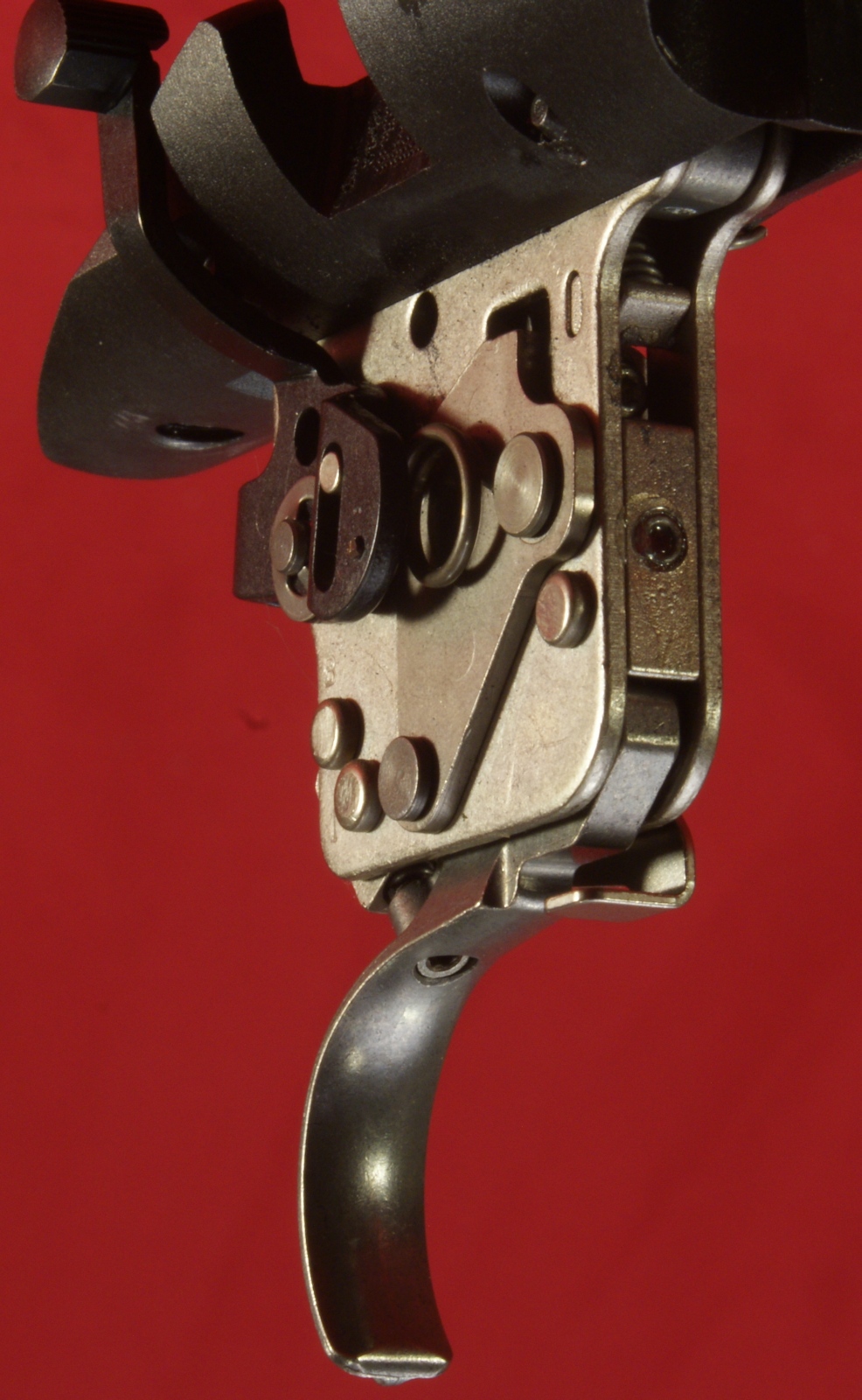
Trigger Assembly
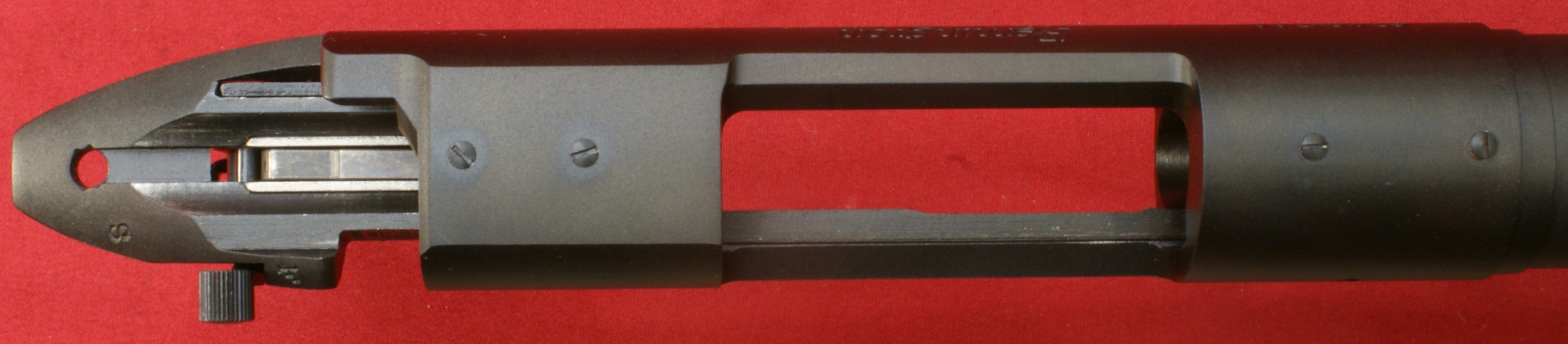
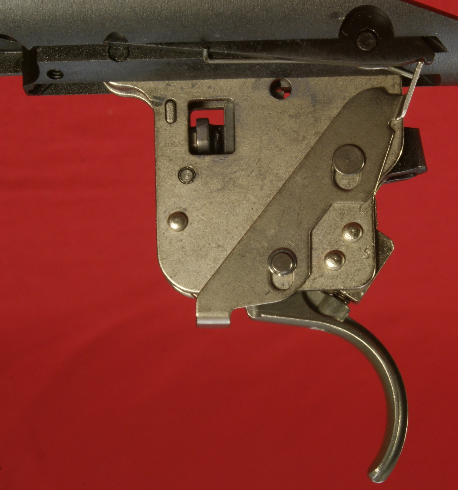
The trigger assembly is held in place by two pins. The trigger assembly shown is the X-Mark Pro Trigger System. The bolt stop lever and safety lever are mounted on the trigger assembly. FYI, the photo below is shown with the safety in the "F" position. When you pull the safety back to the "S" position, the slot in the safety lever causes the pin in the slot to move rearward which brings the over travel arm up against the trigger.
Figure 20

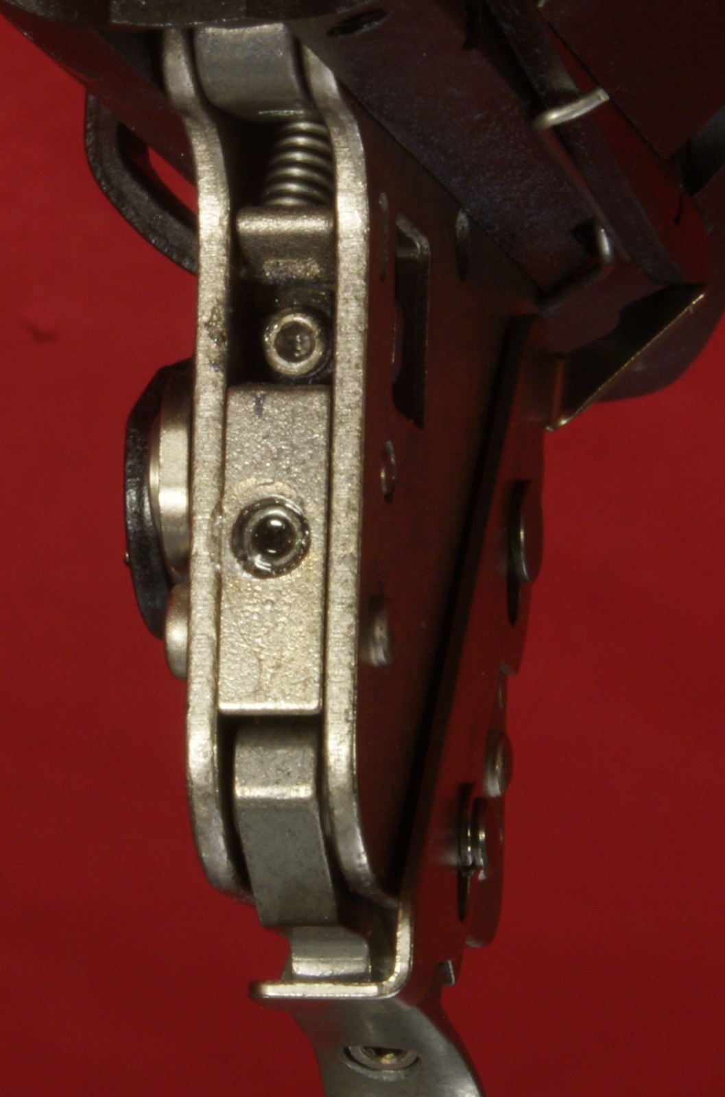
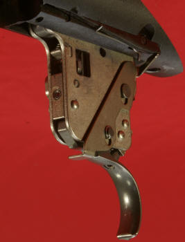
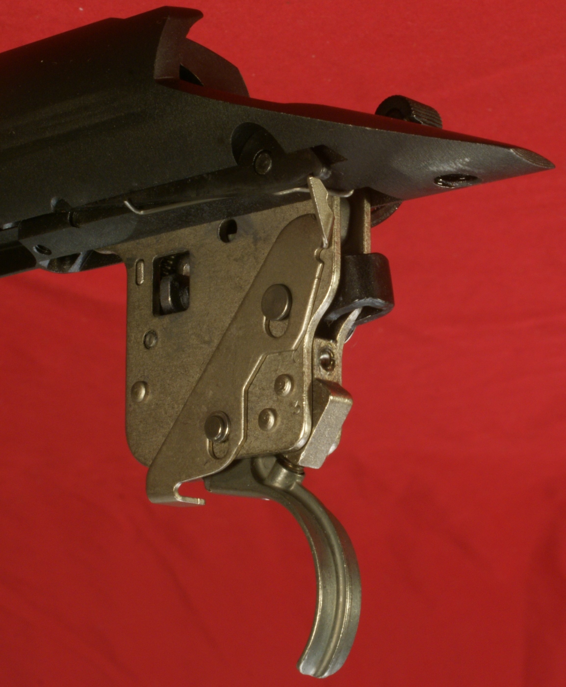
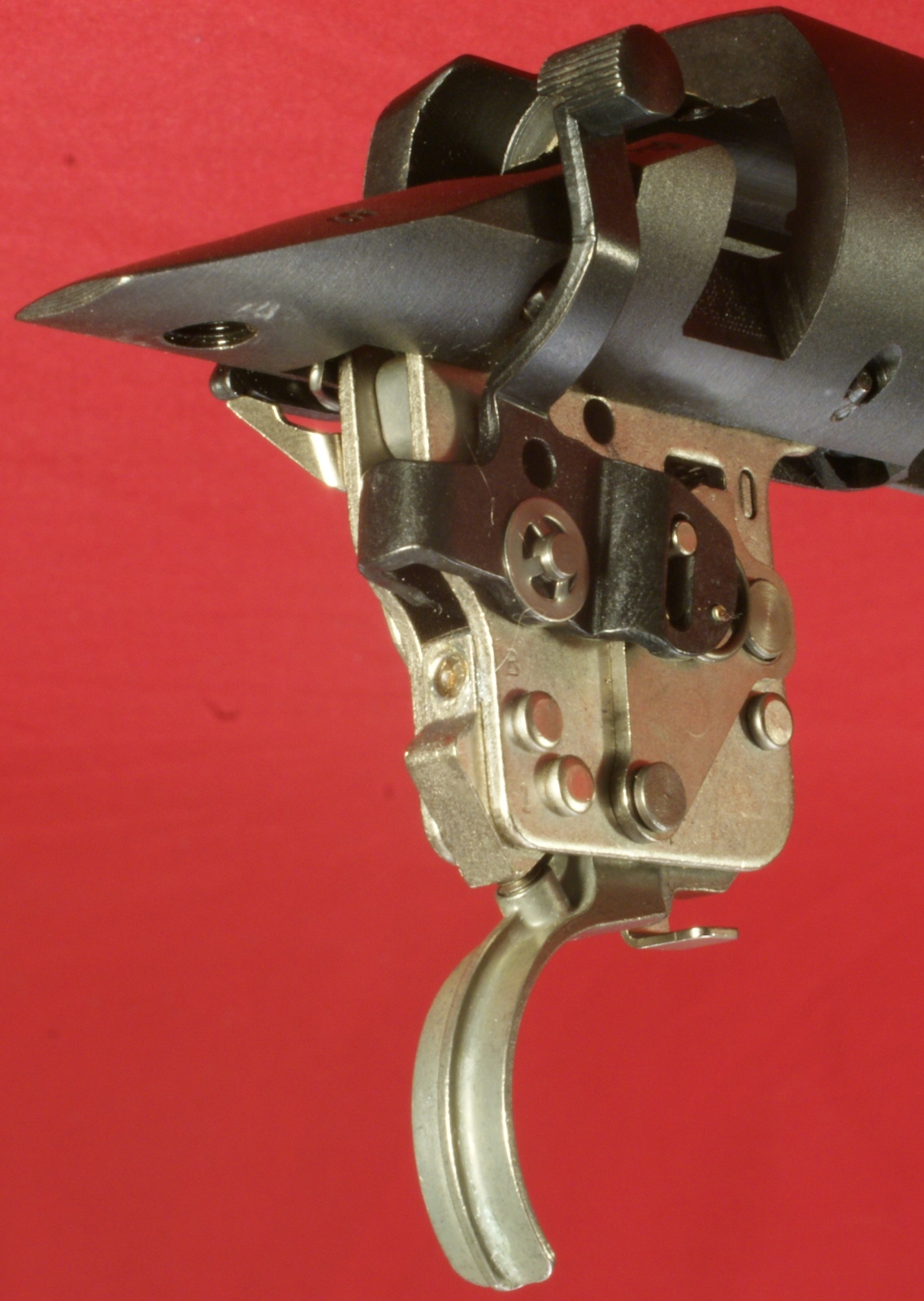
These next three photos give you a good idea of the front of the trigger assembly. There are two screws that have their heads filled with some type of clear epoxy. The top screw is related to over travel and the bottom screw is related to the trigger weight. Also note that the top screw is also on the part of the trigger assembly that makes contact with the trigger when you put the trigger in the safe mode.
Figure 21
Figure 22
Figure 23
On the left side of the trigger assembly you can see the bolt stop lever and how it contacts the bolt stop. Also you can see the hole at the top where you would lubricate your trigger/sear contact surfaces. The trigger should come set from Remington at 3.5 pounds and you should be able to adjust it from 2.5 to 4.5 pounds. One turn of the screw in the trigger is equal to about one pound of adjustment.
Figure 24
On the rear of the trigger assembly is another screw which is the sear engagement screw. Just like with the others, the head of this screw was also filled with some type of epoxy.
Figure 25
Figure 26
I think it is important to understand that Remington puts epoxy in the heads of these screws for a reason. The only screw you should be adjusting is the screw in the trigger body. Tampering with the other screws may void your warranty or even create an unsafe condition that could cause you or someone harm.
Bolt Assembly
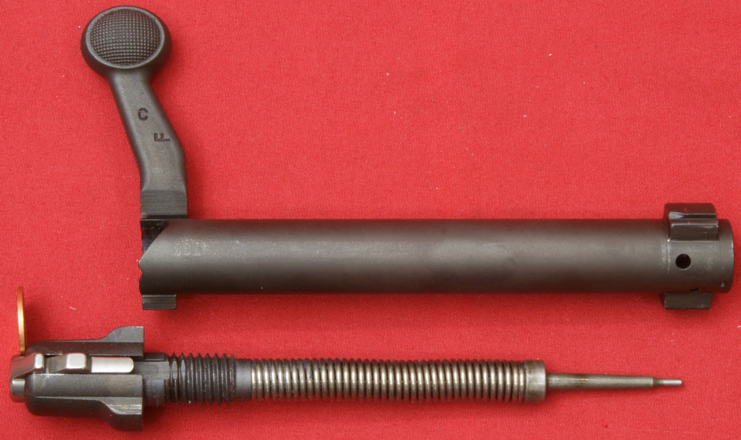
The bolt assembly is made of two primary assemblies which I'm going to call the handle assemble and firing pin assembly. You can see these two assemblies separated in Figure 15 above. The components are made from either some type of low carbon steel or stainless steel.
Figure 27
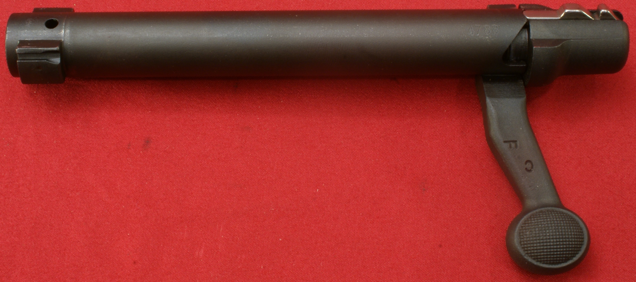
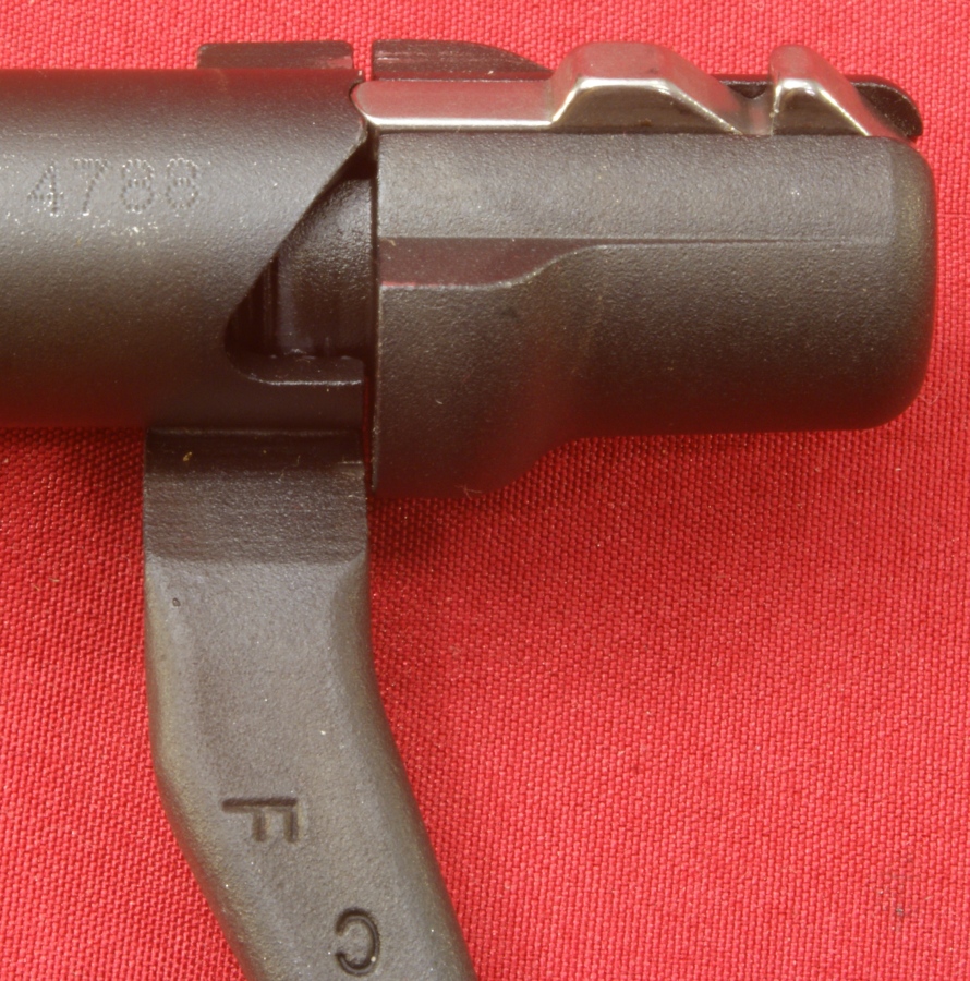
The body of the bolt is dot matrix stamped with the last four digits of the rifle serial number. I believe the "C" and "F" on the bottom of the bolt may also be a date stamp for the bolt.
Figure 28
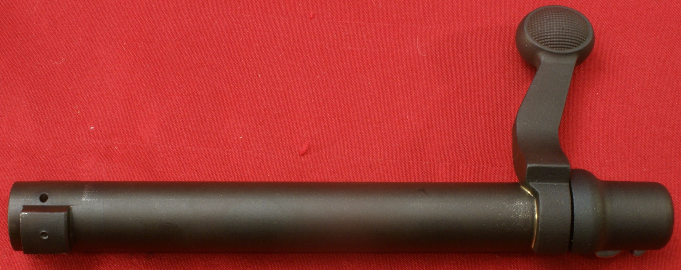
The handle of the bolt is attached to the body of the bolt by silver soldering these two pieces together. You can see the bright line of solder in the corner where these two parts mate.
Figure 29
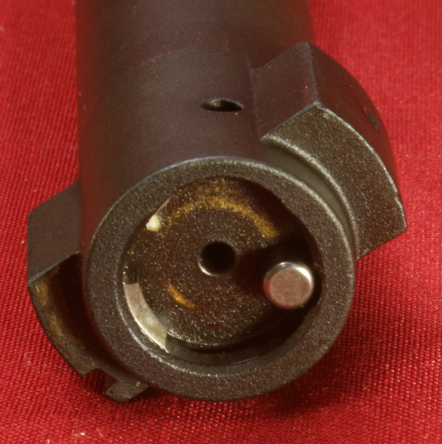
Clearly the bolt has double locking lugs and two more gas ports. One port (hole) is on top in the photo below and the other is own the bottom (not shown). The ejector was very firm and easily pops out the cartridges. The extractor appears to be a clip style extractor that should not be removed for cleaning. If you ever remove the extractor, it is highly recommended to replace the extractor with a new one.
Figure 30
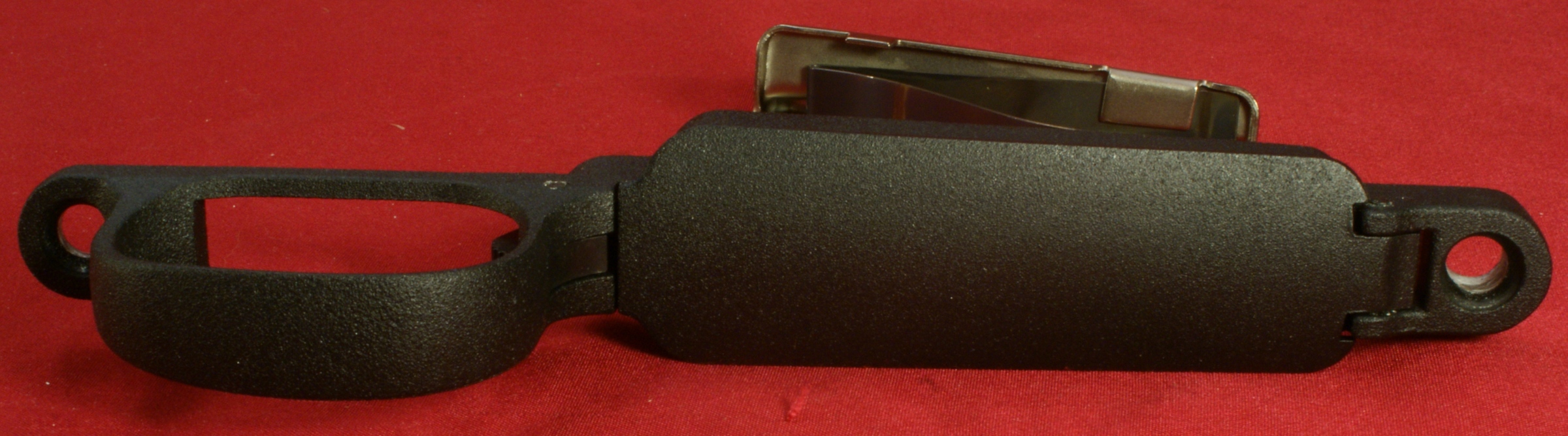
Trigger Guard Assembly
The trigger guard appears to be some type of cast aluminum part that has a rough textured coated surface. The material and coating appear to be the same for the magazine floor plate.
Figure 32
The magazine follower is made from type of stainless steel and the magazine spring from some type of spring steel.
Figure 33
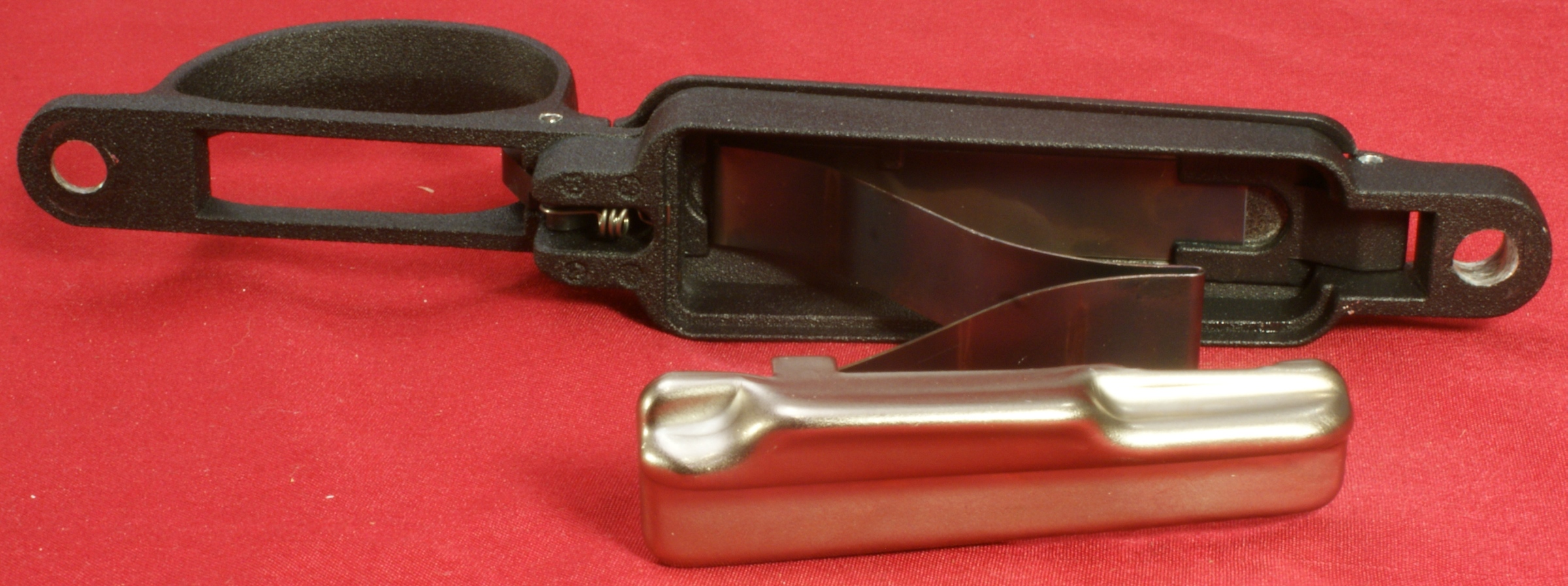
Figure 34
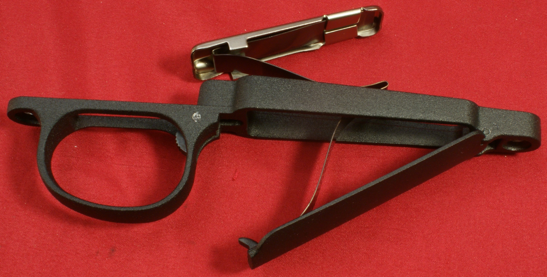
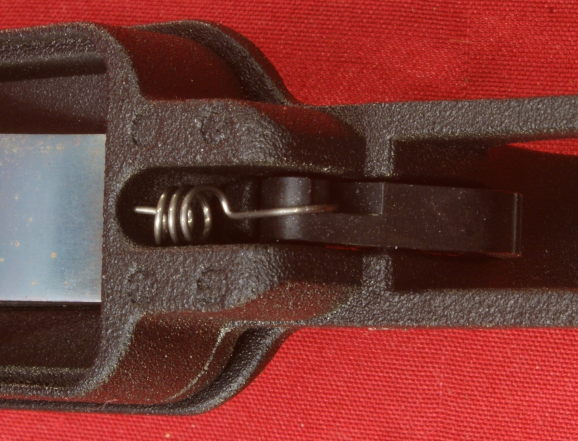
This photo below shows the floor plate latch and latch spring.
Figure 35
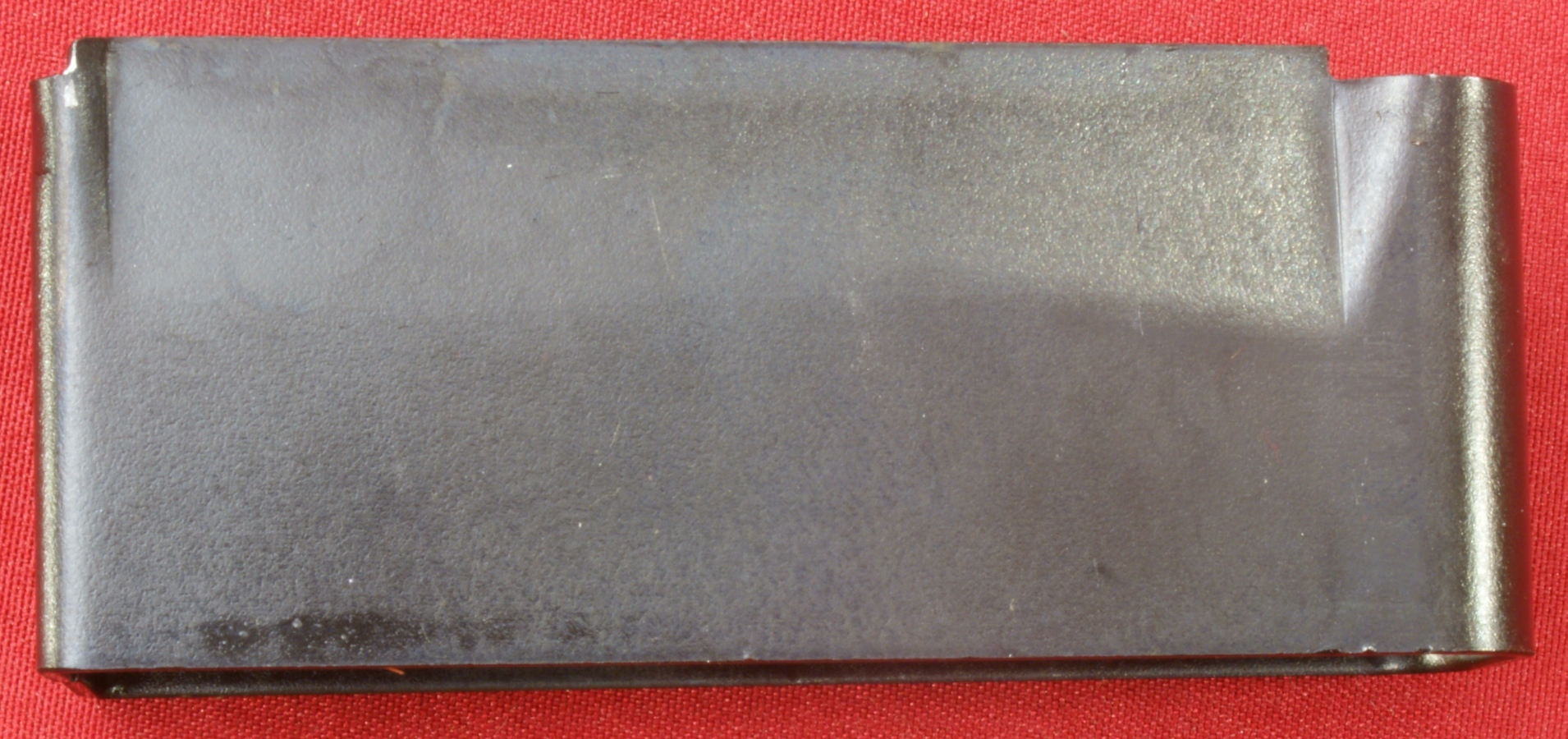
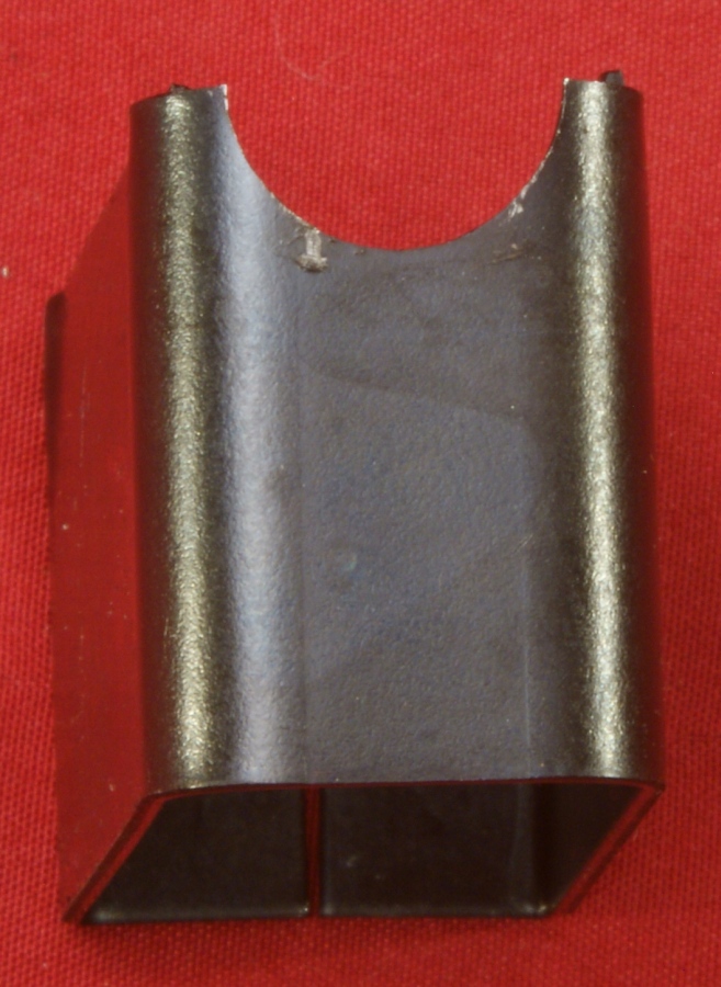
Magazine
The magazine is a very simple bent steel part and houses 4 rounds when fully loaded. It has a half moon cut out in the front to allow for the rounds to feed into the chamber.
Figure 36
Figure 37
Figure 38

Hogue Overmolded Ghillie Green Stock
Since the stock is a Hogue product, I have added a link to the Hogue website so you can see what they say about their stocks. Some of the key points from their website are shown below in colored italics.
- OverMolding provides the ultimate in a comfortable, non-slip, super smooth attractive finish that is durable and extremely quiet.
- The exclusive Cobblestone texture further enhances all Hogue stocks by providing an efficient non-slip, non irritating stippling pattern.
- OverMolded Stocks are constructed by molding a super strong, rigid fiberglass reinforced skeleton or "insert" that precisely fits the guns' action. This rigid skeleton is then OverMolded with a durable but soft synthetic elastomer (rubber). During the heat and extreme pressure of injection molding the elastomer adheres chemically as well as mechanically to the skeleton, resulting in a permanent bond between the rubber and the insert. The super strong skeleton gives the stocks their strength, and the precise molded dimensions provide a perfect drop-in fit of your rifle or shotgun. The state of the art elastomer material used on Hogue stocks won't harden with age and is virtually impervious to all oils and solvents found around firearms, providing years of dependable service.
-
Aluminum pillar bedding is traditionally a gunsmith installed option costing over $100. Our molding process and our desire to produce the best product available compelled us to include pillar bedding as a standard feature. Pillar bedding utilizes aluminum bosses embedded in the stock at critical mounting locations. Aluminum pillar beds guarantee an accurate, rock-solid action fit that will not shoot loose. Aluminum conforms to the rifle action making aluminum superior even to a steel pillar bed. Aluminum pillar bedding is not found standard on any other injection molded stock.
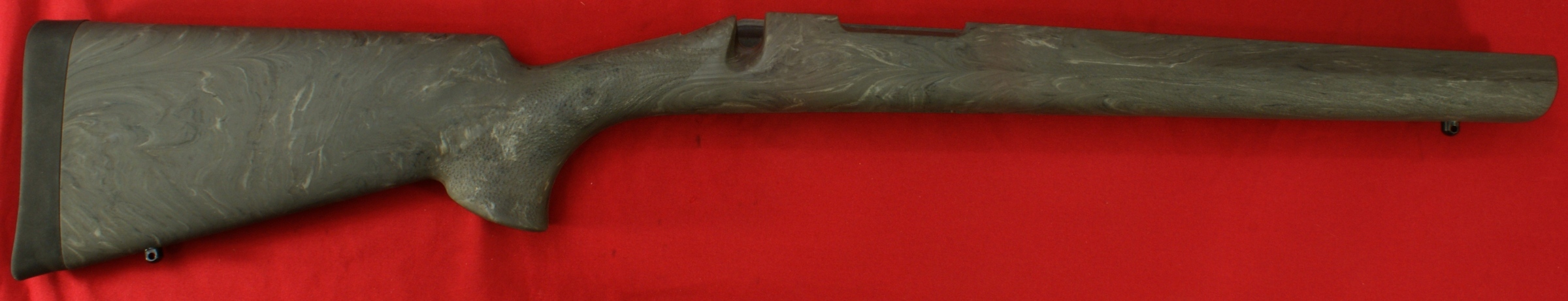
Overall I really like the marble-ish pattern and color of their Ghillie Green stock. Sometimes it is hard to get the colors just right in a photo, but I believe the color of the stock in the photo below matches very closely to the actual rifle.
Figure 39
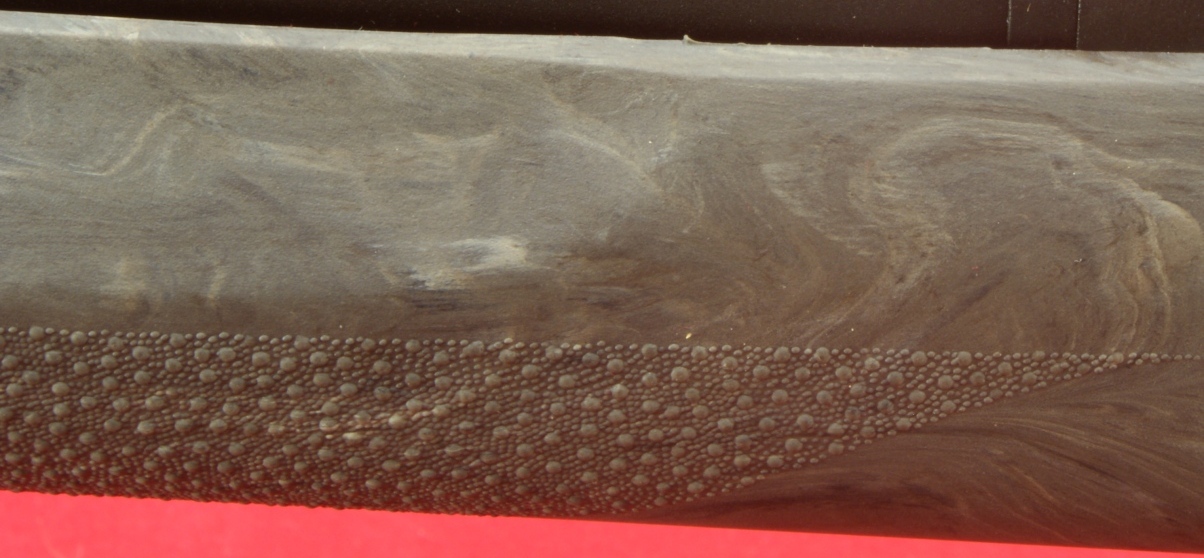
The "cobblestone" texture that Hogue refers to can be seen in this photo stock forearm and I would have to agree this additional texture feels good in my hands.
Figure 40
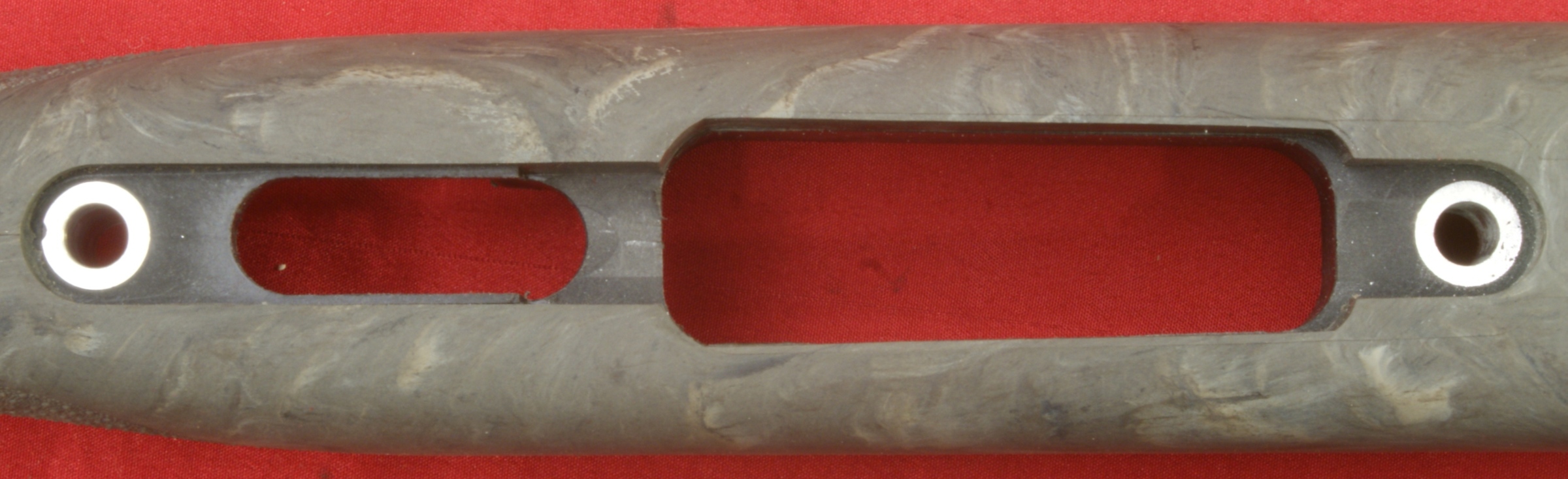
These next two photos show the areas that are molded into the stock that fit either the receiver or trigger guard assembly. If you go back and study some of the photos showing these parts inside the stock (see Part 3), I think you will see that they had a very nice fit. You can also see the top and bottom surfaces of the aluminum pillars. I also agree that these aluminum pillars should produce a higher coefficient of friction at the contact surface of the receiver.
Figure 41
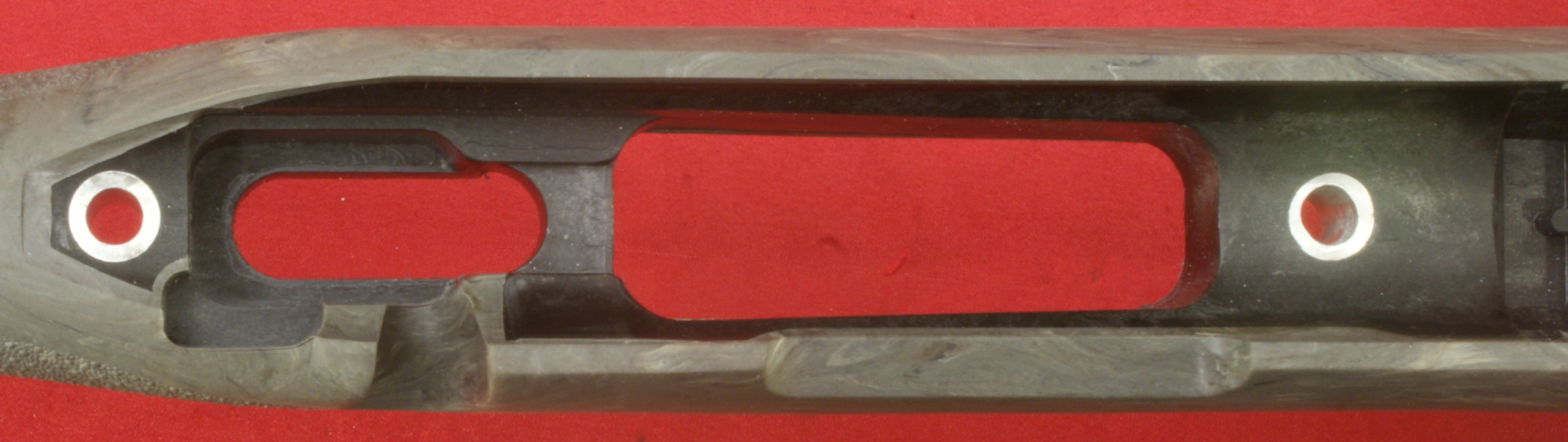
Figure 42
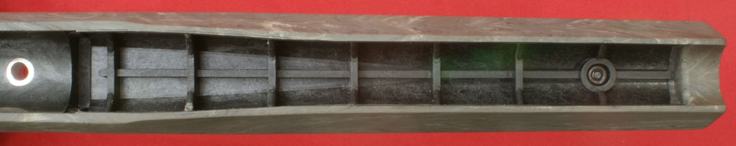
The photo below shows the black "rigid fiberglass reinforced skeleton" that makes up the foundation of the stock.
Figure 43
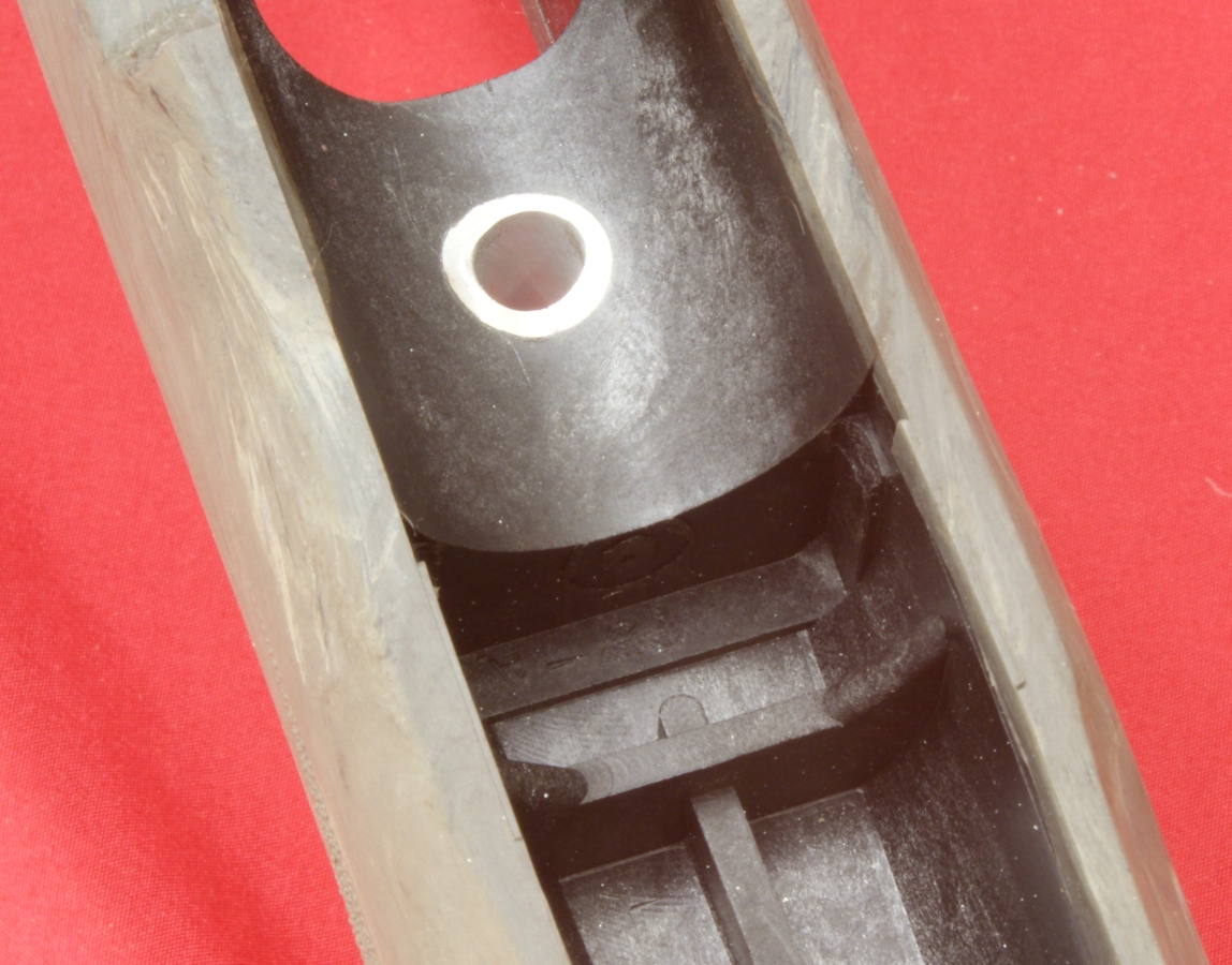
The photo below gives a better view of the area that mates to the recoil lug on the the receiver. You can see the lug bears up against the fiberglass portion of the stock.
Figure 44
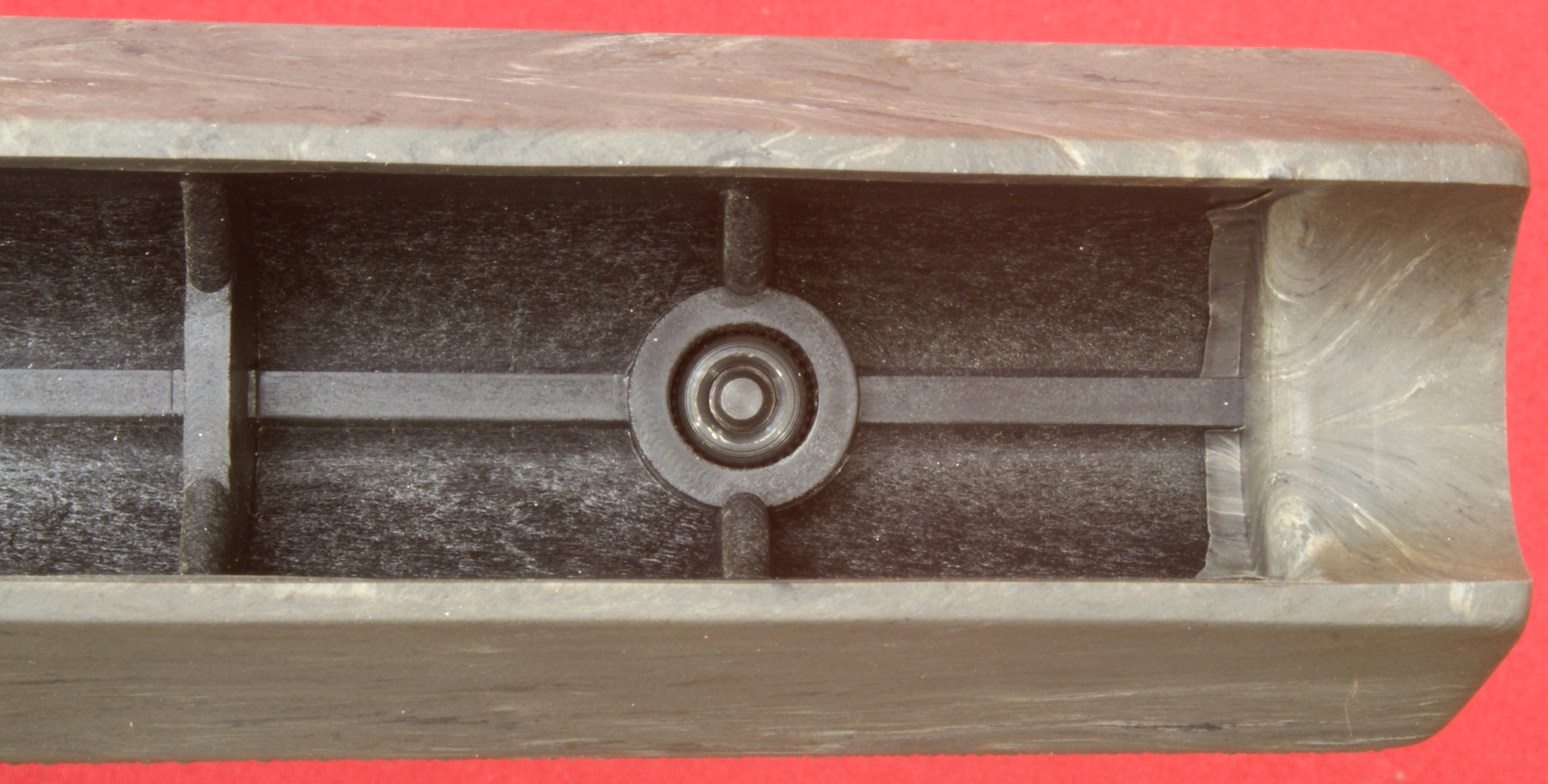
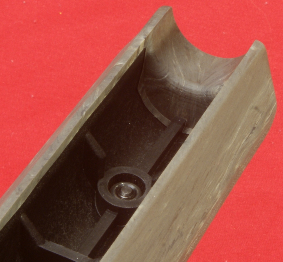
There is a steel insert in the forearm of the stock at the front swivel stud location to prevent stripping of the fiberglass stock when the sling is under load.
Figure 45
The front of the stock has a molded area that gets close to the barrel. On this rifle, this area actually touches the barrel when on a bipod. I plan to sand away some of the rubber OverMolding to relieve this contact.
Figure 46
The recoil pad attaches like most by using two drywall-ish looking screws.
Figure 47
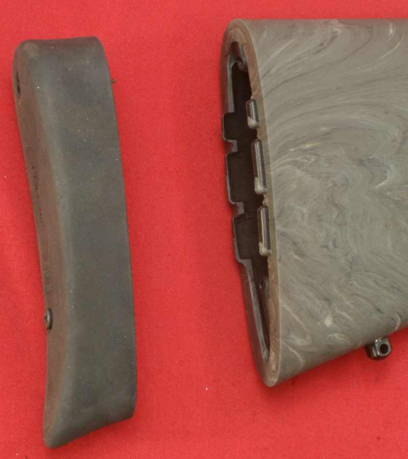
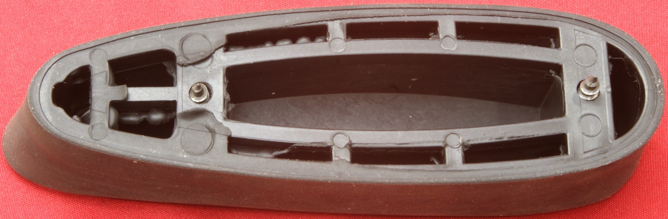
When you flip the recoil pad over, you can see it is not solid. This gives the recoil pad a very soft feel and should help with reducing the felt recoil of the rifle.
Figure 48
Thoughts
The Remington 700 SPS Tactical is a very simple rifle to disassemble, but that is the case for most bolt action rifles. I really like the Hogue OverMolded stock and it appears to have some good features and a good fit. I wish the forearm of the stock didn't lightly touch the barrel on a bipod, but I believe that can be easily corrected by sanding the area under the barrel. The recoil pad is soft and should be effective in reducing felt recoil.
For more detailed photos and commentary, make sure you check out the other parts of this review and feel free to leave comments on my Reader's Comments page. The following links are provided to help you see other parts of this review.
- Remington 700 SPS Tactical Review: Part 1 - Introduction, Specifications and Summary
- Remington 700 SPS Tactical Review: Part 2 - What's in the Box
- Remington 700 SPS Tactical Review: Part 3 - External Features
- Remington 700 SPS Tactical Review: Part 4 - Disassembly and Internal Features (this page)
- Remington 700 SPS Tactical Review: Part 5 - Range Test
Or
If you would like to be notified about future Gunsumer Reports reviews via Facebook, make sure "You Like This" by clicking the Facebook "Like" button at the bottom or top of this page. If it already says "You Like This" beside the button, clicking it again will uncheck the "Like" status and you will not be notified.
| Share on Facebook | |
© 2010, 2011, 2012, 2013, 2014, 2015, 2016, 2017, 2018, 2019, 2020, 2021, 2022, 2023 & 2024 Gunsumer Reports™, All rights reserved.
FTC Disclosure